Download
1 / 15
150 likes | 591 Views
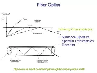
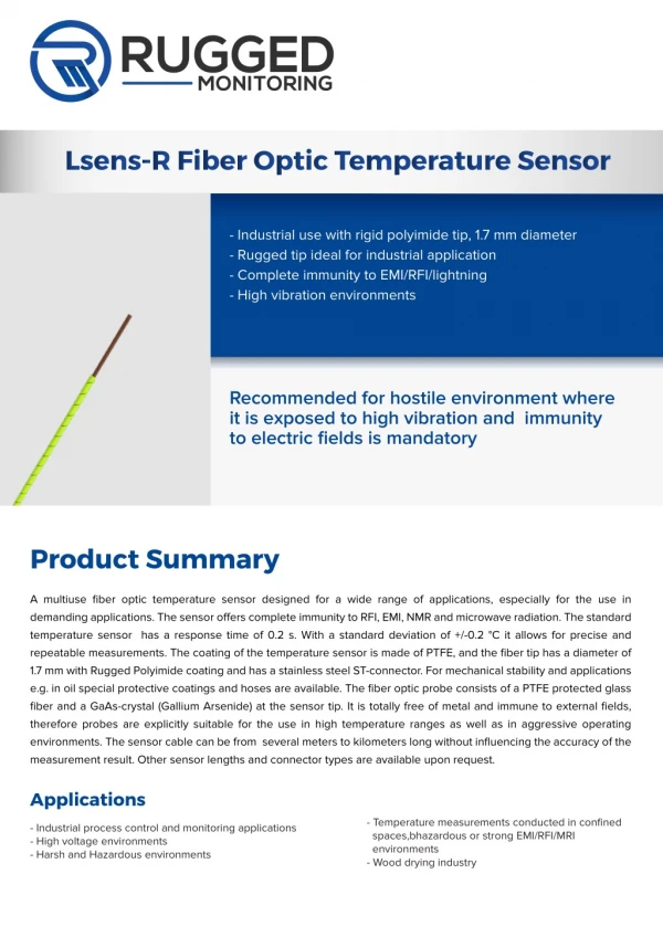
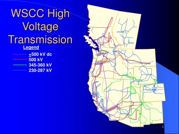
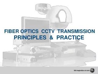
Fiber Optics in High Voltage Transmission Environments. EE 566 October 8, 2003 By: Jason Jones. My Reason for Choosing This Topic…. Find a Combination Between Fiber Optics and Power Engineering This is looking at Fiber Optics in an alternative industry. Fig. 1. Fig. 2. Overview.

E N D
Fiber Optics in High Voltage Transmission Environments EE 566 October 8, 2003 By: Jason Jones
My Reason for Choosing This Topic… • Find a Combination Between Fiber Optics and Power Engineering • This is looking at Fiber Optics in an alternative industry Fig. 1 Fig. 2
Overview • Basics of fiber optic and electrical transmission lines • Different uses of fiber optic cable in the transmission grid system • Employment options • Conclusion/summary
Can high voltage electricity be sent through fiber optics cable? No conclusive evidence or research has shown that it is possible. Only the use of converters, still not practical for long distances and high voltage.
Why use fiber optics with transmission lines? • Sensing and detection of electrical faults and failure(i.e –Supervisory Control and Data Acquisition Systems – S.C.A.D.A) • Can be used as a neutral or ground. • No EMC/EMI issues. • Communication between plants and substations • Extensive ROW (Right Of Way). The cost advantages of existing ROW makes utilities attractive line-leasing partners for many communications carriers.
Fiber optic cables Transmits light (photons) Primarily for communications Electric cables Transmits electricity (electrons) Primarily for powering electrical devices Combination of Two Different Concepts
Most commonly used Fiber Optic • All Dielectric Self Supporting (ADSS) • Wrap type • Optical Ground Wire (OPGW)
Details of ADSS Cables • High fiber count • Cheaper than OPGW • Installed along electrical transmission lines Fig. 3
Details of the OPGW • OPGW is a composite wire which serves as a conventional overhead ground wire, with the added benefit of providing high-capacity and reliable fiber optic communication. Fig. 4
Common Problems • Contamination – fertilizer, pesticides, exhaust, emissions, salt fog. Can only be solved on the design level, difficult because of high voltage design requirements • Space Potential – Electrical potential induced on fiber optic cables • Dry Band Arcing – Caused by the induced current during wet conditions
Space Potential • Induced voltages can be in the tens of kV range. • Causes dry-band voltages and currents. • Causes huge and powerful electric fields. Fig. 5
Dry Band Arcing • Caused by Space Potential and frequency of current in the cable. • Accurse in wet environments • Because of high induced voltage, current can be as low as 1.5mA. Fig. 6
Employment Options • Phillips • Corning • Fiber Planners • The Furukawa Electric Co. • Most power utility companies (i.e. National Grid, Alliant Energy, Duke Energy)
Conclusion/Summary • Many research possibilities. • Very interesting employment. • Good chance of becoming an expert. • High Voltage – BE CAREFUL
References • “Electrical Design Parameters of All-Dielectric-Self-Supporting Fiber Optic Cable”, M.W. Touminen and R.G Olsen, IEEE Transactions on Power Delievery, Vol. 15, No. 3, July 2000 • “Corona Caused Deterioration of ADSS Fiber-Optic Cable on High Voltage Lines”, G.G Karady, G. Besztercey, IEEE Transactions on Power Delievery, Vol. 15, No. 3, October 1999 • “Sensor Design for Leakage Current Measurement on ADSS Fiber-Optic Cable”, G.G Karady, Q, Huang, M.R Hernandez, D. Srinivasan, IEEE 2001 • www.phillips.com • www.pirelli.com • www.controlbylight.com/build/app-nosts/casestudy_hoosier.html • www.navy.mil • www.fiberplanners.com • http://www.sei.co.jp/products_e/illustrated/opgw_e.htm