Download
1 / 77
770 likes | 945 Views
Fiber Optics- Transmission, Receiving & Sensing. Hiba Mahgoub 074094 Ola Ibrahim 074059 Alaa Mohamed Kheiry 0730 21 Yaser Zeidan 074090. Fiber Optics-Introduction, types, advantages & disadvantages and applications. Hiba Mahgoub 074094. Introduction.

E N D
Fiber Optics- Transmission, Receiving & Sensing. HibaMahgoub 074094 Ola Ibrahim 074059 Alaa Mohamed Kheiry073021 YaserZeidan 074090
Fiber Optics-Introduction, types, advantages & disadvantages and applications HibaMahgoub 074094
Introduction Our current “age of technology” is the result of many brilliant inventions and discoveries, but it is our ability to transmit information, and the media we use to do it, that is perhaps most responsible for its evolution.
Introduction-continued Progressing from the copper wire of a century ago to today’s fiber optic cable, our increasing ability to transmit more information, more quickly and over longer distances has expanded the boundaries of our technological development in all areas.
Introduction-continued Today’s low-loss glass fiber optic cable offers almost unlimited bandwidth and unique advantages over all previously developed transmission media. The basic point-to-point fiber optic transmission system consists of three basic elements: the optical transmitter, the fiber optic cable and the optical receiver.
Fiber optics or “optical fiber” • Refers to the medium and the technology associated with the transmission of information as light impulses along a glass or plastic wire or fiber, which acts as a waveguide.
Types of fiber • Fiber is classified into different types : 1. single mode 2. multimode • Based on the way in which the light travels through it,the fiber type is closely related to the diameter of the core .
Advantages • A signal can be sent over long distances • Provides greater capacity than copper or coaxial cable systems. • Can support much higher data rates. • The fiber is totally immune to all kinds of interference. • The fiber optics cables is much smaller and lighter in weight than copper or coaxial cables. Also very flexible and not sensitive to vibration.
Advantages- continued • Optical fibers is guaranteed for 25 years (compared to 10 years guarantee for other systems). • Optical fibers operates in a big range of temperature, typically from -40 to 80. • Since the only carrier in fiber is light, it presents no danger to humans during natural disasters, (like shock during rain storms). • Fiber optics cable is very secure, so it is ideal for secure communication systems.
Disadvantages • Expensive. • Fragility . • Easily damaged from chemical substances. • Requires special skills.
Applications • Telephone & TV Communications • Power Stations • Local Area Networks • Military Applications • Undersea Cables • Traffic signs • Fiber optic sensors
Basic Fiber Optic System & Transmission Ola Ibrahim Mohamed Elhassan 074059
Fiber Optic System Basics
Basic Components of a Fiber Optic System • Optic Transmitter • Optical Fiber Cable • Optic Receiver
Brief Definitions- Continued • The Optical Transmitter: The transmitter converts an electrical analog or digital signal into a corresponding optical signal.
Brief Definitions- Continued • The Fiber Optic Cable: The cable consists of one or more glass fibers, which act as waveguides for the optical signal.
Brief Definitions - Continued • The Optical Receiver: The receiver converts the optical signal back into a replica of the original electrical signal.
Transmitter- Continued • The basic optical transmitter converts electrical input signals into modulated light for transmission over an optical fiber. • Depending on the nature of this signal, the resulting modulated light may be turned on and off or may be linearly varied in intensity between two predetermined levels.
LEDs & LDs • The most common devices used as the light source in optical transmitters are • the light emitting diode (LED) and • the laser diode (LD).
Modulation • Two ways to modulate: • on and off(Digital) • linearly (Analogue)
On-Off Modulation(Digital) • A transistoris used to switch the LED or LD on and off in step with an input digital signal. • This signal can be converted from almost any digital format by the appropriate circuitry, into the correct base drive for the transistor. • Overall speed is then determined by the circuitry and the inherent speed of the LED or LD. Used in this manner, speeds of several hundred megahertz are readily achieved for LEDs and thousands of megahertz for LDs.
On-Off Modulation(Digital) • Digital on/off modulation of an LED or LD can take a number of forms:
Linear Modulation • Linear modulation of an LED or LD is accomplished by the operational amplifier circuit of the previous figure. • The inverting input is used to supply the modulating drive to the LED or LD while the non-inverting input supplies a DC bias reference.
Linear Modulation(Analogue) • Analog modulation can also take a number of forms. • The simplest is intensity modulation where the brightness of an LED is varied in direct step with the variations of the transmitted signal.
Transmission • Several factors must be considered for the transmission itself:
Amplifiers or Repeaters • To overcome the effects of attenuation in the fiber, we must introduce repeaters at intervals to amplify the signals. • This involves a light detector to convert the signal from light to an electrical signal. The electrical signal is then amplified and used to power another light source for the next section of fiber.
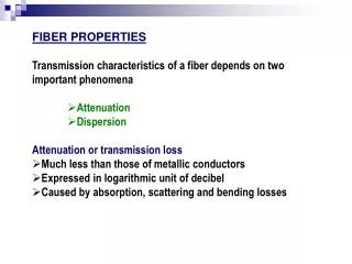
Attenuation • Fiber attenuation, which necessitates the use of amplification systems, is caused by a combination of material absorption, Rayleigh scattering, Mie scattering, and connection losses. • Other forms of attenuation are caused by physical stresses to the fiber, microscopic fluctuations in density, and imperfect splicing techniques.
Bandwidth • All of the above attenuation factors result in simple attenuation that is independent of bandwidth. In other words, a 3 dB loss means that 50% of the light will be lost whether it is being modulated at10Hz or 100 MHz. • There is an actual bandwidth limitation of optical fiber however, and this is measured in MHz per km.
Bandwidth • As the figure above illustrates, a ray of light that enters a fiber relatively straight or at a slight angle (M1) has a shorter path through the fiber than light which enters at an • angle close to the maximum acceptance angle (M2). As a result, different rays (or modes) of light reach the end of fiber at different times, even though the original source is the same LED or LD. • This produces a “smearing” effect or uncertainty as to where the start and end of the pulse occurs at the output end of the fiber - which in turn limits the maximum frequency that can be transmitted.
Bandwidth- Continued • The number of modes is reduced is by making the core of the fiber as small as possible. • Single-mode fiber has a much higher bandwidth because it allows only a few modes of light to propagate along its core. • Fibers with a wider core diameter, allow many more modes to propagate and are therefore referred to as Multimode fibers.
Bandwidth- Continued • Typical bandwidth for common fibers range from a few MHz per km for very large core fibers, to hundreds of MHz per km for standard multimode fiber, to thousands of MHz per km for single-mode fibers.
Transmission windows • Each effect that contributes to attenuation and dispersion depends on the optical wavelength. • The wavelength bands (or windows) that exist where these effects are weakest are the most favorable for transmission. • These windows have been standardized, and the currently defined bands are the following:
Connectors & Optical Receivers Alaa Mohamed Kheiry 073021
Optical Connectors • Optical connectors are the means by which fiber optic cable is usually connected to peripheral equipment and to other fibers. • These connectors are similar to their electrical counterparts in function and outward appearance but are actually high precision devices. • In operation, the connector centers the small fiber so that its light gathering core lies directly over and in line with the light source (or other fiber) to tolerances of a few ten thousandths of an inch.
Optical Connectors • The most popular type of multimode connector in use today is the ST connector. This connector uses a twist lock type of design and provides lower overall losses. • A typical mated pair of ST connectors will exhibit less than 1 dB (20%) of loss. • The inclusion of an “anti-rotation tab” assures that every time the connectors are mated, the fibers always return to the same rotational position assuring constant, uniform performance.