Download
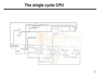
1 / 22
220 likes | 370 Views
Single-cycle mixed-fluid LNG (PRICO) process. Part II: Optimal operation Sigurd Skogestad & Jørgen Bauck Jensen Quatar, January 2009. Single-cycle mixed fluid LNG process. Natural gas: Feed at 40 bar and 30 °C Cooled to -157 °C Δ P = 5 bar in main heat exchanger.

E N D
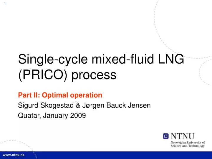
Single-cycle mixed-fluid LNG (PRICO) process Part II: Optimal operation Sigurd Skogestad & Jørgen Bauck Jensen Quatar, January 2009
Single-cycle mixed fluid LNG process Natural gas: • Feed at 40 bar and 30 °C • Cooled to -157 °C • ΔP = 5 bar in main heat exchanger
Single-cycle mixed fluid LNG process 30 bar Refrigerant: • Partly condensed with sea water • Cooled to ~ -157 °C • Expansion to ~ 4 bar • Evaporates in main HX • Super-heated 10°C • Compressed to ~ 30 bar 4 bar Sup 10 °C -157 °C 19 bar
Degrees of freedom Manipulated variables: • Compressor speed N • Choke valve opening z • Turbine speed • Sea water flowrate • Natural gas feed flowrate 6-9. Composition of refrigerant (4) 6-9
Degrees of freedom Assumptions: • Assume maximum cooling in SW cooler • Realized by fixing T=30 °C • 8 degrees of freedom for optimization • 4 degrees of freedom in operation • Assume 4 constant compositions in operation
Operational constraints • Some super-heating to avoid damage to compressor • Maximum LNG temperature before expansion -157 °C • Gives the amount of flash gas • Maximum compressor power 120 MW • Maximum compressor rotational speed is 100 % • Minimum distance to surge is 0 kg/s (no back-off)
Optimization problem • Assume same prize for feed and fuel • Reasonable since feed may be used as fuel • Neglect income of turbine work • The main effect of the liquid turbines is the extra cooling effect, not the power production • Neglect cost of cooling with sea water • Sea water requires pumping which is cheap in operation compared with compressors
Mode I: Nominal optimum • Feed flowrate is given (69.8 kg/s) • 8 - 1 = 7 steady-state degrees of freedom (incl. 4 compositions) • Three operational constraints are active at optimum • Temperature of natural gas after cooling at maximum (-157 °C) • Compressor surge margin at minimum (0.0 kg/s) • Compressor speed at maximum (100 %) • Only the four degrees of freedom related to refrigerant compositions are unconstrained
Mode II: Nominal optimum • LNG production is maximized • 8 steady-state degrees of freedom (incl. 4 compositions) • Four operational constraints are active at optimum • Compressor work Ws at maximum (120 MW) • Compressor surge margin at minimum (0.0 kg/s) • Temperature of natural gas after cooling at maximum (-157 °C) • Compressor speed at maximum (100 %) • Note that two capacity constraints are active (1 and 4) • Only the four constraints related to refrigerant composition are unconstrained
Nominal compressor operating point for mode II N=100% (max speed) N=50% N=10% * Surge limit
Optimum with disturbances • 4 operational degrees of freedom • Refrigerant composition is constant during operation • -1; Always optimal to have minimum cooling • Natural gas is cooled to -157 °C • -1; One degree of freedom is used to set the load • Mode I: The production rate is given • Mode II: The compressor work is at maximum (Ws = 120 MW) • = 2 unconstrained degrees of freedom for both modes
Optimum with disturbances • Two additional degrees of freedom were at constraints at the nominal optimum • Compressor rotational speed at maximum (100 %) • Compressor surge margin at minimum (0.0 kg/s) • We also find that controlling these constraints gives close to optimal operation with disturbance
Optimum with disturbances • Strictly speaking we would need to consider the following four regions: • This is complicated and we prefer to have the same controlled variables in all four regions • Control the nominal active constraints and
Mode II; production vs. disturbance • Dots are re-optimized • Lines are for different controlled variables constant • Constant distance to surge (0.0 kg/s) • N=Nmax gives highest production • N=Nmax is the only feasible control structure in the increasing load direction
Conclusion • Maximum compressor speed and minimum distance to surge is nominally optimal for mode I and mode II • In practice one would have a back-off from surge, but this would still be an active constraint • This is also close to optimal or optimal for all disturbance regions • Control the following variables: • Maximum sea water cooling (valve fully open) • TLNG = -157 °C • LNG flowrate = 69.8 kg/s (mode I) or Ws = 120 MW (mode II)
Additional material • Disturbances considered • Structure of model equations • Data used for the PRICO process