Download

1 / 7
70 likes | 281 Views
WISP. Content. Hardware Architecture Microcontroller MSP430F2132 Operating Modes & Interrupts Code High-level States Communication Layer. Hardware Architecture. Voltage Supervisor + Voltage Regulator. Antenna gets RF signal. External Voltage Supervisor tells MCU when to wake up

E N D
Content • Hardware Architecture • Microcontroller • MSP430F2132 • Operating Modes & Interrupts • Code • High-level States • Communication Layer
Hardware Architecture Voltage Supervisor + Voltage Regulator Antenna gets RF signal • External Voltage Supervisor tells MCU when to wake up • MCU processes bits and performs Gen 2 protocol • Polls sensors to gather data Maximize power transfer to Power Harvester Interprets signal into bits + converts bit voltage level to be Vreg RF signal rectified into DC voltage Transistor that changes antenna impedance for ‘backscatter’
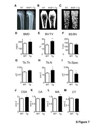
Microcontroller MSP430F2132 Architecture General Information Frequency 16 MHz Flash/ROM 8 KB RAM 512 Bytes Information Memory 256 Bytes Clock System ACLK 32.7 MHz watch crystal MCLK Used by CPU SMCLK Used by Peripheral Modules Consumed by RFID • RAM – variables. Small chunk used • Port 1 Interrupt used for Communication. • Port 2 Interrupt used for Voltage Supervisor – can be shared • Port 3 for debugging (no interrupt capability) • 2 Timer counter interrupts (one used for communication) • Used 4 pins total out of 24 GPIO
Microcontroller Operating Modes Interrupts Types • Non-Maskable: NMI pin, Oscillator fault, flash access violation • Maskable: Peripherals and WDT in Interval Mode > 1 peripheral interrupt pending simultaneously • In 2132: • Comparator • Brownout Protection • RAM • Flash • …higher priority > WDT Available Interrupts vs. Sleep State Active Mode All Interrupts LPM0, LPM1, LPM2, LPM3 ADC, WDT, Timer, External LPM4 External Interrupt Processing NORMAL GIE on by developer NESTED Available Clocks vs. Sleep State GIE on by developer Interrupt Service Routine Active Mode All Clocks. CPU active (~200uA/MHz) Interrupt Service Routine Interrupt Service Routine • GIE turned off by Hardware • Interrupt serviced • GIE turned on by Hardware • GIE turned off by Hardware • GIE turned on by developer LPM0/1 All Clocks. CPU off (~30uA/MHz) LPM2/3 DCO off. LFOSC on. CPU off (~1uA @ ~10kHz) LPM4 All disabled (0.1uA) New Interrupt serviced w/o priority All pre-Interrupt settings in place
Code High-Level States
Code Communication Layer EPC State Machine Transmit Receive Port 1 Interrupt & GIE Enabled Setup to Receive LPM4 No Timer value wrt bit length & encoding Enough # bits Port 1 Interrupt Yes No Correct Command Timer Interrupt Enabled Yes Process packet Port 1.1 delimiterNotFound = 1 Flip Port 1 transmit pin at timer interrupt Timer Reset at every positive edge Each bit pushed into register Timer not reset (i.e. no bit) WISP breaks out of communication layer