Download
1 / 53
530 likes | 628 Views
Muon Campus Beam Transport January 23, 2013 J. Morgan. What we have now – the Pbar source. Recycler Ring. P1 - P2 - M 1. M 3. Delivery Ring. AP-50. MI-8 Line. AP-30. AP-10. Muon Campus. R. Ray - Director's CD-1 Review. R. Ray - Mu2e Collaboration Meeting. Antiproton Source

E N D
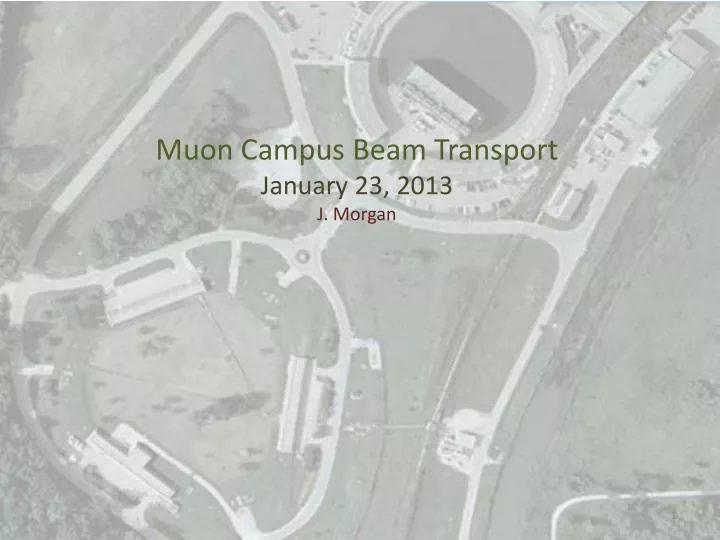
Muon Campus Beam Transport January 23, 2013 J. Morgan
What we have now – the Pbar source J. Morgan
Recycler Ring P1 - P2 - M1 M3 Delivery Ring AP-50 MI-8 Line AP-30 AP-10 Muon Campus R. Ray - Director's CD-1 Review R. Ray - Mu2e Collaboration Meeting J. Morgan
Antiproton Source Beam lines • A 120 GeV/c proton beam is transported to the Target Station via AP-1 every 2.2 seconds • An 8.89 GeV/c negative secondary beam travels down AP-2 and is injected into the Debuncher • 8.89 GeV/c antiprotons are bunch rotated and stochastically cooled in the Debuncher, then transferred to the Accumulator via the D/A line • Antiprotons are accumulated over hours, then transferred to MI via the AP-3 and AP-1 lines • 8.89 GeV/c protons can be “reverse injected” or sent in the reciprocal direction of the antiprotons for tune-up J. Morgan
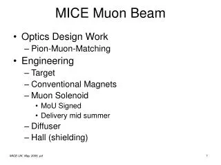
Muon Campus Configuration • The Accumulator and D/A line are no longer needed and will be used for beamline components • M1 is the new name for AP-1, apertures will be improved to accommodate the larger 8.89 GeV/c primary beam • AP-2 will be renamed M2 and will be a dedicated beam line for g-2 • The M3 line will connect to the Delivery Ring (Debuncher) in the D30 straight section • Both the g-2 secondary beam and Mu2e proton beam will be transported to the Ring via M3 • M2 and M3 will have a higher quadrupole density than AP-2 did (~4.4 m vs. ~13.0 m) for g-2 • Extraction, both single turn for g-2 and resonant for Mu2e, are also in the D30 straight section • The old injection region for AP-2 will become an abort for Mu2e and could be used for proton removal for g-2 • The new extraction line will be called M4 • The g-2 line connects M4 to the Storage Ring J. Morgan
Reconfiguring Pbar Antiproton production Muon Campus J. Morgan
Challenges and Technical Risks • High intensity 8 GeV proton beam in M1 (and M3 for Mu2e) • Much larger beam size in beamlines upstream of AP0 • Beam loss must be kept extremely low • Much higher intensity for Mu2e in Rings enclosure • Bunch formation takes place in Recycler • Incoming beam has increased momentum spread • Average cycle time is much faster than for Pbar • Factor of 13 for Mu2e, 26 for g-2 • New kicker power supplies needed • Pulsed septum based on Booster BSE • AP-3 beam line will be reconfigured for compatibility with g-2 • Secondary beam line for g-2 (M2) connects to M3 • g-2 requires dense quadrupole spacing to minimize beta functions • Old upstream AP-3 lattice must be matched to downstream M3 lattice for Mu2e • Beam is injected and extracted into the Delivery (Debuncher) Ring in D30 • New M3 to Delivery Ring connection faces logistical challenges • g-2 fast extraction as well as Mu2e resonant extraction must be supported • Mu2e will require substantial radiation shielding for injection and extraction devices • M4 line must transport both Mu2e and g-2 beams to their experimental halls Delivery Ring Future injection region J. Morgan
Muon g-2 Beam lines • The P1, P2 and M1 lines will transport an 8.89 GeV/c proton bunch, 120 ns long, to the Target Station at an average rate of 12 Hz, with 100 Hz bursts (16 bunches, 10 ms interval) • Downstream of the Target Station, the M2 line will carry the 3.1 GeV/c secondary beam 150 m until it connects with M3 • Some of the pions decay into 3.09 GeV/c muons as they travel down M2/M3 • The M2 and M3 lines have an increased quadrupole density to improve muon yield • The M3 line connects to the Delivery Ring after an additional 130 m and is injected in the 30 straight section • Muons can circle the 550 meter Delivery Ring as many times as desired • The abort located in the 50 straight section can be used to remove protons (requires multiple turns) • 3.09 GeV/c muons are extracted into the M4 line, then bent into the g-2 line for transport to the Storage Ring in the MC-1 building Target Station J. Morgan
Mu2e Beam lines • An 8.89 GeV/c proton bunch, 120 ns long, is transported to the Debuncher via M1 and M3 (bypassing the Target Station) at an average rate of 6 Hz with 18 Hz bursts • The 8.89 GeV/c bunch is injected into the Delivery Ring in the 30 straight section with a pulsed septum and kicker • A 2.5 MHz RF system maintains the short bunch as it circulates in the Delivery Ring • The proton bunch is resonantly extracted with electrostatic septa and a Lambertson into the M4 line • The M4 line transports short proton “micro-bunches” to an external Target Station to produce an intense muon beam • The remaining proton beam that is not resonantly extracted is aborted in the 50 straight section and transported to an absorber J. Morgan
Possible Beamline Project Responsibility J. Morgan
8 GeV protons to the Target Station • RR to P1 stub line optics has been being integrated into entire line • Needed to reconcile different MAD and OPTIM files • Optimization of optics underway to reduce beam size through lines • Magnet choices for aperture improvements has been refined • Surplus Tevatron B2 magnets will be used at V714 • Lower beam momentum for g-2 allows the use of weaker and/or shorter magnets in M1, but will limit the peak beam energy to about 40 GeV • A CDA Cooling Ring dipole will be used at F-17 in place of the C-magnets • Pbar MDC magnets will be used in the HV100 and HV102 bend strings • Smaller aperture trim will be replaced with Pbar NDA and NDB trims • Beam spot size specification has been reduced • Spot size requirements has been reduced from σxy = 0.55 mm to 0.15 mm • Final Focus region will incorporate a quadrupole triplet • Final 3Q120 quadrupole will be replaced by three Pbar SQx quads • Triplet configuration will greatly reduce the peak β functions in the M1 line • SQx quadrupoles will have a large enough aperture for high efficiency transmission and small spot size at the Target • Instrumentation • Existing BPM, Toroid and SEM/SWIC systems can be used with minimal modification • Tevatron BLM electronics will be repurposed to upgrade legacy equipment J. Morgan
RR to Target MAD file Meiqin Xiao Jim Budlong J. Morgan
120 GeV Pbar production MI to Target Station 8 GeV Muon production RR to Target Station
Planned improvements HV100 dipoles MI-52 Lam. / V701 C-magnets Tev. F0 Lambertsons removed Larger trims V714 C-magnets F-17 C-Magnets HV102 dipoles Quad triplet J. Morgan
Final focus region in M1 SQx triplet Vault Wall ValeriLevedev J. Morgan
Injection lines to Debuncher – M2 & M3 • Target Station to M3 line (M2) • Four magnet quadrupole “triplet” remains at beginning of line • β functions peak around 80 - 100 m in IQ2 and IQ3 (limiting aperture) • Junction between lines is located 100 – 125 m from Target Vault wall • 4.4 m Quadrupole spacing with 90 phase advance • M2 to M3 connection • Original optics plan required the removal of a 20 ton dipole magnet in Right Bends to switch between g-2 and Mu2e • Present design does not require magnet removal, but has six dipole magnets which adds considerable cost • M3 line to Delivery Ring • Challenging design constraints to match optics and trajectory into Ring • Optics design has two elevation changes and a 5 horizontal bend • Confined area for magnet supports in area over Delivery Ring • Need >30 inches between Delivery Ring and M3 to allow use of existing pbar magnets • Must be compatible with injection scheme into Delivery Ring • Optics must match and acceptance must be at least 40 pi-mm-mr for g-2 • Instrumentation • g-2 will use upgraded SEM’s and new ion chambers, possibly wall current monitors • Mu2e will use existing BPM and SEM systems, plus upgraded toroid electronics J. Morgan
Target Station to Delivery Ring (g-2)AP-2 removed and replaced by M2 line,which connects to M3 line M2 18.5o Bend M3 M2→M3 IQ07 → IQ13 RemainIn Situ ~13.33m separation John Johnstone J. Morgan
M2 to M3 Line Cross-over Mod B1 “Switch” 5’ somethings C-mag SDE M3 SDE g-2 beam offset ~3.75” John Johnstone M2 J. Morgan
M2 to M3 Line Cross-overalternative scheme John Johnstone J. Morgan
Mu2e beam pathto Delivery Ring • M3 line will branch from M1 (AP-1) line and bypass Target Station as AP-3 line does now • M3 line between the Target Station bypass and the M2/M3 line merge needs to be reconfigured to match new downstream lattice (140 m), has not been done yet • M3 line downstream of M2/M3 line merge must be designed to accommodate both g-2 and Mu2e beams • High intensity 8.89 GeV/c protons instead of 3.1 GeV/c secondary beam Target Station bypass J. Morgan
M3 line into Delivery Ring John Johnstone End of last slide J. Morgan
D30, AP-3 line Crossover area D30, AP-3 line above Debuncher, D3Q6 on left Injection line layout – horizontal bend in D30 J. Morgan
Delivery Ring • Injection from M3 line • All injection bends are vertical – mature design completed • Modified Main Injector C-Magnet for initial bend • Injected beam passes through Pbar LQ magnet ~130 mm above centerline • Modified Booster septum magnet provides the greatest bend • Two module injection kicker system puts beam on D.R. closed orbit • Injection scheme preserves 40 pi-mm-mr acceptance or greater • Is also compatible with Mu2e 8.89 GeV/c protons • 30 straight section reconfiguration • Present optics plan requires removal of dipole magnet in Right Bends • Need to design connection that allows accommodates Mu2e proton beam down M3 while preserving small β functions for g-2 • Proton Removal • Incorporates abort system required for Mu2e • Multiple D.R. revolutions required to adequately separate protons from muons • Extraction to M4 line • Lambertson magnet required to accommodate Mu2e resonant extraction • Either modified NOvA design or new design • 8Q32 quadrupole (from BNL?) at D5Q5 • C-Magnet follows quadrupole, identical to what will be used for injection • Dual kicker schemes for both dedicated g-2 running and Mu2e/g-2 running J. Morgan
Delivery Ring Kickers • Reuse existing Debuncher kickers • Reduced cost and labor effort • Pool of available equipment limited to Pbar and Tevatron • Power supplies can’t be reused in most cases • Kickers rise and fall times will be specified as 95%/5% • Losses from injection and extraction must be kept to a minimum • Must eliminate “tail” on Accumulator injection kicker • Maintain or improve existing apertures • Existing kicker locations retained whenever possible • Try to avoid lattice modifications to accommodate kickers • Beam line layout can remain the same • Reduced kicker magnet options due to space constraints • Use the fewest power supply components possible • Keep power supply costs as low as possible • Limited space available in service buildings J. Morgan
Kicker locations and rates Extraction kicker Abort/proton removal kicker Injection kicker J. Morgan
Kicker rise and fall times J. Morgan
Injection Region Bend angles of Septum, LQ and C-Magnet Injection region John Johnstone – M3 line optics J. Morgan
g-2 vertical injection trajectory (with and without vertical bump) J. Morgan
Mu2e vertical injection trajectory J. Morgan
Delivery Ring Mu2e Abort • Section of AP-2 used for abort line • Abort absorber located in Transport tunnel (using existing E760 collimator) • Relatively low beam power (1.92 kW) so cooling water system is not needed • Requires one new Vertical bending magnet J. Morgan
Doing “laps” in the Delivery Ring -and using the Mu2e abort for proton removal- • Target Station to Debuncher distance is about 285 meters • Muon and proton centroids separate by about 40 ns • Debuncher circumference is 505 meters • 363 meters between injection at D3Q3 and abort at D4Q5 (51 ns) • Muon and proton centroids separate by about 70 ns per turn • Bunch length is about 120 ns • Centroid separation to abort on first turn is 91 ns, second turn 161 ns, etc. • Removing protons cleanly versus less cleanly • Roughly 1e13 protons per hour, based on Cary’s simulations and momentum aperture • “Clean” removal would require kicker to fully rise in gap between protons and muons • “Less clean” removal requires kicker gap to be about half as wide • Mu2e abort has a 450 ns rise time “as is” • Around 7 turns in the Debuncher to remove protons cleanly • 5 turns to eliminate them, but remove them less cleanly • Existing kickers could rise in 200 ns with a power supply upgrade • Around 4 turns for clean removal, 3 turns for less clean • Would require 2 power supplies operating in parallel instead of 1, at a cost of about 400 k$ • “Straight through” distance to g-2 is about 425 meters • Would need Wein filter or other means to remove protons J. Morgan
Proton Removal • Issues, progress and work to be done • Target Station to Delivery Ring distance will be about 290 meters • Muon and proton centroids separate by about 40 ns • Injection kickers and abort at D4Q5 is 352 meters (50 ns) • Debuncher circumference is 505 meters • Muon and proton centroids separate by about 70 ns per turn • Bunch length is about 120 ns (possibly with satellites) • Centroid separation to abort on first turn is 91 ns, second turn 161 ns, etc. • Removing protons cleanly versus less cleanly • Roughly 1e13 protons per hour, based on Cary’s simulations and momentum aperture • “Clean” removal would require kicker to fully rise in gap between protons and muons • “Less clean” removal requires less gap between beams or affects part of muons • Mu2e abort has a 440 ns rise time “as is” • Mu2e has a 120 ns bunch length, Delivery Ring revolution period is ~ 1,700 ns • Around 7 turns in the Debuncher to remove protons completely • 6 turns to eliminate 90% of protons without disturbing muons • Existing kickers could rise in 200 ns with a power supply upgrade • Around 5 turns for clean removal, 4 turns for less clean • Would require 2 power supplies operating in parallel instead of 1, at a cost of about 700 k$ • “Straight through” distance to g-2 is about 425 meters J. Morgan
Protons slipping in time Drawing by T. Leveling J. Morgan
Delivery Ring Extraction • Issues, progress and work to be done • Extraction layout is driven by resonantly extracted beam for Mu2e • Electrostatic septa surrounding D2Q3 bend beam horizontally ~1 mr each • Mu2e resonantly extracted protons have much smaller emittance than g-2 muons • Lambertson is required for Mu2e to work with electrostatic septa • A large aperture quadrupole is required at D2Q5, larger than Pbar LQx • An 8Q32 quadrupole and C-Magnet both provide additional vertical bends • Mu2e has Delivery Ring optics that are unfavorable for maximizing Ring acceptance • Different optics and different horizontal trajectories are needed for g-2 and Mu2e • A large horizontal bump across the extraction region is used for g-2 • g-2 needs an extraction kicker for beam to enter the M4 line • Best location for kickers is where Mu2e septa will eventually reside • Two kicker layouts are planned for g-2 dedicated running vs. “dual mode” • A two kicker system will be used for g-2 dedicated running • Existing Pbar kickers can be used as originally designed • For dual mode, a single module can be used(a benefit of the 3.09 GeV/c momentum) with a altered impedance to increase strength • Extraction scheme provides 40 pi-mm-mr acceptance for g-2 and a common extraction channel for both experiments J. Morgan
g-2 extraction trajectories Horizontal bump across extraction region (note different scales) Bump created by motorized quadrupoles at 203, 204, 206 and 207 J. Morgan
Mu2e extraction trajectory (horizontal bump removed) J. Morgan
Extraction kicker layouts g-2 operation and Mu2e beamline commissioning (uses Pbar EKIK modules with 12.5Ω impedance) Dual mode – either g-2 or Mu2e can run (uses Pbar IKIK modules with 8.33Ωimpedance) J. Morgan
Extraction Region Bend angles of Lambertson, LQ and C-Magnet 8Q32 40 pi-mm-mr beam envelopes Extraction region Carol Johnstone – M4 line optics J. Morgan
Extraction kickers Injection kickers Horizontal bend (5) Vertical bend Extraction Lambertson and C-magnet Injection Septum and C-magnet Vertical bends g-2 operation and Mu2e commissioning J. Morgan
Extraction septa (Mu2e) Extraction kicker (g-2) Injection kickers Horizontal bend (5) Vertical bend Extraction Lambertson and C-magnet Injection Septum and C-magnet Vertical bends Dual running mode configuration J. Morgan
Extraction beamlines (M4 and g-2) • M4 Line • Extraction trajectory from D.R. has been reconciled with entry into M4 line • First 20 m of line must fit above Delivery Ring, line is 30” above Delivery Ring • Elevation change to 48” above Delivery Ring is completed before Left Bend • Location of Left Bend is critical to location of MC-1 (g-2) and Mu2e buildings • MC-1 building is highly constrained by road and utility corridors • Mu2e building also constrained to east and north • Process of eliminating mechanical conflicts and using available pbar magnets or known designs has shifted bend downstream • This shiftedM4 line tunnel too close to the MC-1 building • Left Bend dipole configuration has been changed to increase total bend to ~40° • M4 line from Left Bend to Mu2e must incorporate several features • Extinction • Diagnostic dump • Final Focus • g-2 Line • Optics design is conceptual, less mature than other lines • Geometry of M4 and g-2 lines at “split” needs to be carefully designed • Momentum collimation needs to be incorporated into end of bend region • An additional elevation change of 6 feet is required to get to Storage Ring level • Line will be mostly populated with BNL magnets from old g-2 beamline • Match into Storage Ring will drive design of downstream part of line J. Morgan
External beam lines J. Morgan
Split between the M4 and g-2 lines SDEW dipoles in diagram are now 6-3-120’s • g-2 line splits from M4 line in the middle of the left bends • Momentum collimation will be integrated into Left Bend • g-2 line is roughly 50 m long • Vertical dogleg will make elevation change to experiment • Final focus and matching to Storage Ring will be designed in collaboration with Ring Team J. Morgan 43
g-2 Storage Ring 10 cm beam access port J. Morgan
g-2 Line J. Morgan
Accelerator ControlsDelivery Ring and Transport Risks • The communications duct that carries all Ethernet and Controls signals between the Muon service buildings and the control system will be dug up during extraction beamline construction. • New fiber optic cable will be pulled to AP-30 to reestablish Ethernet connectivity. • Heliax cables will be spliced and rerouted to AP30 to restore the remaining Controls connectivity. • Cost for this ($70K M&S plus labor) should be absorbed by g-2 or FESS GPP. • Fiber optic and heliax cable provide controls connectivity between the three Delivery Ring service buildings via cable pulls that go through the accelerator tunnel. • Careful assessment of radiation levels where fiber optic controls cables exist must be taken into account. • Single mode fiber optic cable pulled on the Accumulator side of the enclosure should provide the necessary functionality at a minimal cost. • More robust radiation hardened upgrade options are available ($45K - 90K M&S plus labor) and are covered by the risk registry. • Controls Ethernet that runs to the AP-0, F23 and F27 buildings use legacy systems that will be asked to perform at the peak of their abilities. • It is assumed the existing networks will function at an adequate level. • Upgrade options ($50K - $100K M&S plus labor) are available and covered by the risk registry. • Fiber optic cable will be pulled to the Mu2e service building to provide controls connectivity. • Cost ($35K M&S plus labor) for this will be covered in the External Beamlines Controls BoE. Communications Duct bank to be replaced X No fiber to AP0 (Legacy Thickwire) No fiber to F23 & F27 (wireless) J. Morgan
Magnets made available by reconfiguration of Rings and beam lines J. Morgan
FNAL and BNL Quadrupole availability and needs for beam lines J. Morgan SQ LQ 4Q24