Download
1 / 19
210 likes | 691 Views
One Side Welding Submerged Arc Welding Process. Welding in Shipbuilding Conference May 10-11, 2011 by Sean P Moran. Outline of Presentation. Introduction of the Process Procedure for Application Weld Evaluation Results Supporting Discussion Summary. Introduction of the Process.

E N D
One Side Welding Submerged Arc Welding Process Welding in Shipbuilding Conference May 10-11, 2011 by Sean P Moran
Outline of Presentation • Introduction of the Process • Procedure for Application • Weld Evaluation Results • Supporting Discussion • Summary
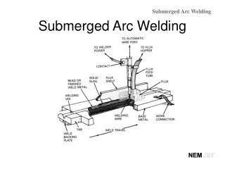
Introduction of the Process • Submerged Arc Welding (SAW) Application • Multiple Wire Tandem Procedure • Single (One) Side Full Penetration Welds • Weld Travel Speeds Capable of 60 IPM
Advantages, SAW-OSW • Reduce Production Time • Eliminate the Additional Cost of Equipment Needed to Rotate the Plates for Two-Sided Welds • Capable of Achieving Full-Penetration Square Butt Seams in ¼” Plate From One Side • Excellent Welder Appeal – Ease of Use
Limitations, SAW-OSW • Limited Fit Up Robustness • Fixture and Clamping • Flux Bed Mechanism and Procedure • Multiple Weld Head Requirements
Procedure for Application • Tandem Welding Process using DC Lead and AC Trail • Solid Wire Lead using Solid and Tubular Wire Trail • Square Butt Joint Preparation with 0 – 1/8 Gaps • Non-Floating 1½” Width and 9/32” Depth Flux Bed • Copper Chill Bar with 1½” x 1/16” Center Recess
Weld Joint Fit Up • Two ¼” x 2” x 18” hot rolled plates with ¼” x 2” x 9 run off tabs at either end • Set two 18” bars side by side, set the gap, weld tabs and 3 tack welds at ¼, ½ & ¾ of plate length
Equipment Selection • PEH Controls • LAF 1000 DC • TAF 800 AC • A6 Wire feeders • Knurled Feed Rolls for (Tubular Wire)
Equipment Set Up • Electrode angle 90º Lead 65º Trail • 3/4" Distance between electrodes
Welding Consumables • DC/AC - 1/8” Spoolarc 81 Solid Wire • EM12K • DC/AC - 1/8” Alloy Shield 70S Tubular Wire • EC1-H8 • Welding Flux: OK Flux 10.71 • F7A5 • Backing Flux: OK Flux 10.69 • No AWS Classification
Application Set Up • 2½” x 1½” x 6’ copper chill with 1½” x 1/16” center recess • OK Flux 10.69 applied over the top of the chill • Excess flux screen off forming a 7/32” crown
Supporting Discussion • Travel Speeds Approaching 60 IPM • Excellent Full Penetration Profiles • Increase Face Reinforcement with Tubular Wire • Gap Size of 1/8” Prove to Have Limited Robustness
Future Work • Varying Gap Width of 0 - .5T • Increase and Alter Electrode Diameters • Robust .5T Full Length Gap • Evaluate Mechanical Weld Properties
Summary • One Sides Full Penetration SAW • Tandem with Either Solid or Tubular Trail • Robust Gap Widths of 3/32 inch • Weld Travels Speeds Approaching 60 IPM • User Friendly - Ease of Operator Use