Download
1 / 21
230 likes | 465 Views
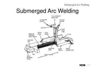
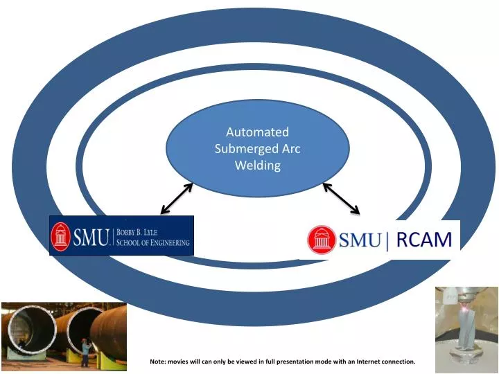
Automated Submerged Arc Welding. Note: movies will can only be viewed in full presentation mode with an Internet connection. Objective is to achieve high-quality welds. By eliminating or minimizing Lack of Fusion Lack of Penetration Undercuts Slag Entrapment Porosity

E N D
Automated Submerged Arc Welding Note: movies will can only be viewed in full presentation mode with an Internet connection.
Objective is to achieve high-quality welds • By eliminating or minimizing • Lack of Fusion • Lack of Penetration • Undercuts • Slag Entrapment • Porosity • Repair or Re-Weld Cost • By improving • Seam Shape • Surface Finish • Weld Strength and Toughness • Bead Placement http://met-tech.com/images/crane-failure-15.jpg • This could be achieved by: • seam tracking • adaptive fill control
Characteristics of the developed laser-based machine Vision System • CMOS GigE with high resolution, high frame rate up to 200 fps • Directed streaming of image signal into network card ( no need for dedicated frame grabber) • The distance to transfer data up to 100 m or 333 ft, especially of importance in the case of welding large structures such as wind turbine. • PC-based controller of a 3-axis positioning system (no need for a proprietary integrated circuit board. • Software based on LabView
Automated Seam Tracking for Submerged Arc Welding Shape of groove Workpieces with groove Width of groove Depth of groove Laser Machine Vision System Area of groove Stand-off distance Mismatch Motion Control System Actual position of tracking point Desired position of tracking point
Automated Fill Control for Submerged Arc Welding Shape of groove/bead Area of groove/bead Weld Model Width of groove/bead Depth of groove/bead Stand-off distance Temperature distribution Laser Machine Vision System Arc Voltage Geometry of groove/bead SAW Machine Current / WFS Travel Speed
Developed Laser-based Machine Vision System at the Research Center for Advanced Manufacturing • Schematic presentation of • laser machine vision system • (b) Photo oflaser machine vision system installed at the 3-axis PC-based controlled positioning system
Control panel of the developed laser machine vision system workpiece profile 3D profile tracking error
Application of Laser Machine Vision System as Measuring Instrument width : 25.4 mm depth : 15.9 mm (a) coupon as measurement target (b) configuration of measurement process (c) Movies recorded during measurement process • Note: movies will can only be viewed in full presentation mode.
Seam Tracking Control (a) top and side view of the setup for seam tracking both along X and Z direction (b) Flowchart of the close-loop controller for seam tracking along two axes
Movies of Laser Machine Vision System for Seam Tracking Control (a) when seam tracking is not activated (click images to play) • (b) when seam tracking is activated (click images to play)
The Results for Seam Tracking Control (a) position error of tracking point when seam tracking is not activated (b) position error of tracking point when seam tracking is activated
Laser Machine Vision System for Post-Weld Inspection (a) couponfor post weld inspection (b) configuration of inspection system (c) movies showing inspection process (click images to play) Note: movies will can only be viewed in full presentation mode.
Results of Post-Weld Inspection (a) coupon as post inspection target (b) 3D-view of the profile of the coupon • (c)top-view of the profile of the coupon (d) side-view of the profile of the coupon
Weld cross-section calculation for adaptive fill control Width of weld Height of clad Weld A × vw=vf × π×d2/4 A-cross-sectional area of the weld d- diameter of filler wire Vw-welding speed Vf-wire feed rate A2 A=A1+A2 A A1
Simulation of Adaptive Fill Control scan “A” scan “A” Level of current for scan “A” Modeled heat transfer in the molten pool for scan “A”
Case Analysis 1 Simple Straight Butt Weld
Case Analysis 2 Circumferential Weld
Case Analysis 2 (click to play the movie above) Note: Movies can only be viewed in full presentation mode
We can always improve it as needed Thanks for your attention !!!