Download
1 / 58
580 likes | 610 Views
The Architecture of Artificial-Gravity Habitats. Theodore W. Hall. Future in Space Operations (FISO) Colloquium 17 November 2010. 1. The Architecture of Artificial-Gravity Habitats. Theodore W. Hall. Future in Space Operations (FISO) Colloquium 17 November 2010. 2. Education: Architecture

E N D
The Architecture ofArtificial-Gravity Habitats Theodore W. Hall Future in Space Operations (FISO) Colloquium17 November 2010 1
The Architecture ofArtificial-Gravity Habitats Theodore W. Hall Future in Space Operations (FISO) Colloquium17 November 2010 2
Education: Architecture B.S. ’79, M.Arch. ’81, Arch.D. ’94: University of Michigan Experience: Software Development ’80-’94: Systems Research ProgrammerArchitecture and Planning Research LaboratoryUniversity of Michigan ’94-’04: Postdoctoral Fellow & Research OfficerDepartment of ArchitectureChinese University of Hong Kong ’09- Research Computer SpecialistUniversity of Michigan 3D Lab (UM3D) “Expensive Hobby”: Space Architecture • Dissertation: “The Architecture of Artificial-Gravity Environmentsfor Long-Duration Space Habitation” • http://www.artificial-gravity.com/ • http://www.spacearchitect.org/ My Background. 3
Adverse Effects of Micro Gravity: • Fluid redistribution • Fluid loss • Electrolyte imbalances • Cardiovascular changes • Red blood cell loss • Muscle damage • Bone damage • Hypecalcemia Why Artificial Gravity? 4
Adverse Effects of Micro Gravity: • Immune suppression • Cell membrane thickening • Vertigo and disorientation • Nausea and malaise • Exercise incapacity • Olfactory suppression • Weight loss • Flatulence Why Artificial Gravity? 5
Adverse Effects of Micro Gravity: • Facial distortion • Postural changes • Coordination changes Why Artificial Gravity? 6
Tsiolkovsky, 1903 Noordung, 1928 von Braun, 1952 Lockheed Corp., 1960 Historical Concepts. 8
NASA LaRC & North American, 1962 Inflatable concept, 1962 Historical Concepts. 9
Fundamental weaknesses: • Too abstract. • Too precise. • Too difficult to read. Comfort charts. 15
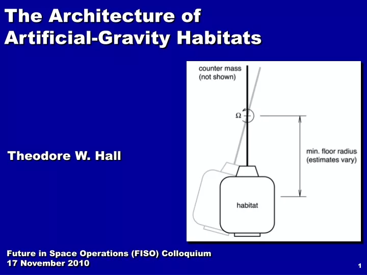
min. radius and velocitymin. mass and energy Artificial gravity at the limits of “comfort”. 27
R = 67.1 mV = 14.0 m/sv = 1.0 m/sx = 3.8 mslope = 4º = 7% grade = 1:15 Apparent slope at min. agreed “comfort” R & V. 37
R = 67.1 mV = 14.0 m/sv = –0.5 m/sx = 0.0 mlean = 4º Apparent slope at min. agreed “comfort” R & V. 38
“BNTR Artificial Gravity Mars Mission.”[Borowski, Dudzinski, Sauls, Minsaas, 2006] Greater apparent slope at smaller R & V. 39
Acent = 0.38 gW = 4.0 rpmR = 21.2 mV = 8.9 m/s “BNTR Artificial Gravity Mars Mission.”[Borowski, Dudzinski, Sauls, Minsaas, 2006] Greater apparent slope at smaller R & V. 40
“BNTR Artificial Gravity Mars Mission.”[Borowski, Dudzinski, Sauls, Minsaas, 2006] Greater apparent slope at smaller R & V. 41
floor slope = 13ºladder lean = 6º “BNTR Artificial Gravity Mars Mission.”[Borowski, Dudzinski, Sauls, Minsaas, 2006] Greater apparent slope at smaller R & V. 42
“2001: A Space Odyssey.”[Kubrick, Clarke, 1968] Ladder in side wall – not recommended. 43
“2001: A Space Odyssey.”[Kubrick, Clarke, 1968] Ladder in side wall – apparent lean. 44
“VGRS.”[Emmart, 1989] Ladder in side wall – not recommended. 45
Axial Most comfortable: • No Coriolis. • No apparent slope. • No floor curvature. • No ladders. • No gravity gradient. Least stable? • Twists to tangential. Module Orientation. 46
Tangential Medium comfortable: • Coriolis. • Apparent slope. • Floor curvature. • No ladders. • No gravity gradient. Medium stable: • Needs balance. Module Orientation. 47
Radial Least comfortable: • Coriolis. • Ladders. • Gravity gradients. • Disoriented plan. Most stable. Module Orientation. 48