Download

1 / 23
230 likes | 400 Views
Towards Automating Patient-Specific Finite Element Model Development. Finite Element Method. Invaluable tool in musculoskeletal research Demands associated with modeling the geometrically complex structures of the human body often limit its utility – restricting analyses to baseline models

E N D
Towards Automating Patient-Specific Finite Element Model Development
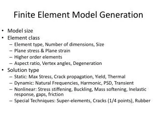
Finite Element Method • Invaluable tool in musculoskeletal research • Demands associated with modeling the geometrically complex structures of the human body often limit its utility – restricting analyses to baseline models • Conventional meshing techniques often prove inadequate
Patient Specific Models • In order to bring FE to the “bedside” for guiding surgical procedures the technique must be unencumbered from the image segmentation and mesh generation process • Overcome the limitations associated with individualized, or patient-specific models
FE Model Development Acquire Medical Imaging Data Surface Generation Mesh Generation Segment Regions of Interest Apply Boundary/Load Conditions and Material Properties Finite Element Analysis
Objective • Automate the generation of high quality hexahedral meshes • Projection method • Mapped Meshing • Inclusion of soft tissues such as cartilage • Automated Segmentation • Neural network • Level set • EM Segmentation • Validation • Segmentation using surface scanning • FE analysis using physical testing
Bones of Interest Why initiate with the bones of the hand? • Long bones and cuboidal bones • Number of bones per cadaveric specimen • Readily extended to the other bones of the body
Bones of Interest Extend to irregular bones such as the vertebrae
Segmentation of ROIs • Manual Segmentation • Establish manual rater reliability and validity • Automated segmentation • Neural network algorithm • EM Segmentation • Level Set Segmentation
Segmentation Validation • Cadeveric specimens dissected and scanned using a 3D laser scanner • Physical scan surface co-registered with CT surface representation using ICP registration • Distance between manual and automated definitions compared to physical scans
Projection Method Carpal Bone Bounding Box with Assigned Mesh Seeding Projected Mesh Initial Bounding Box
Extending Projection Method • A single bounding box coupled with the projection technique may not always prove sufficient • Method has been extended to add multiple boxes and/or subdivide existing boxes
Subject Surface Overlap After Registration Template Mesh Initial Overlap Mapped Meshing • Map a template mesh to a new subject • Use FE framework in ITK • Apply forces based on distance from mesh surface to surface representation ITK FEM Registration
Solid Mesh Smoothing • Projection of initial mesh onto the surface oftentimes yields distorted elements • Need to smooth resulting mesh – Iterative Laplacian smoothing for solid mesh • Method • Apply Laplacian smoothing to surface nodes holding interior nodes fixed • Project nodes back onto the original surface • Smooth interior nodes with surface nodes held fixed • Iterate for specified number of iterations or until convergence threshold is reached
Results of Mesh Smoothing Unsmoothed Smoothed Unsmoothed Smoothed
Mesh Quality Check • Aspect Ratio: Excess of 100 to 1 • Distorted Isoparametric Elements: • Angle between isoparametric lines • < 45 degrees or > 135 degrees
Acknowledgements • Grant funding • R21 (NIBIB - EB001501) • R01 (NIBIB - EB005973) • Steve Pieper, Simon Warfield, Curt Lisle • Kiran H. Shivanna, Nicole Kallemeyn, Nicole DeVries, Esther Gassman, Ritesh Bafna, Srinivas Tadepalli, Dr. Brian Adams