Download
1 / 44
610 likes | 1.01k Views
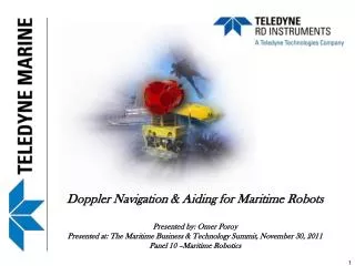
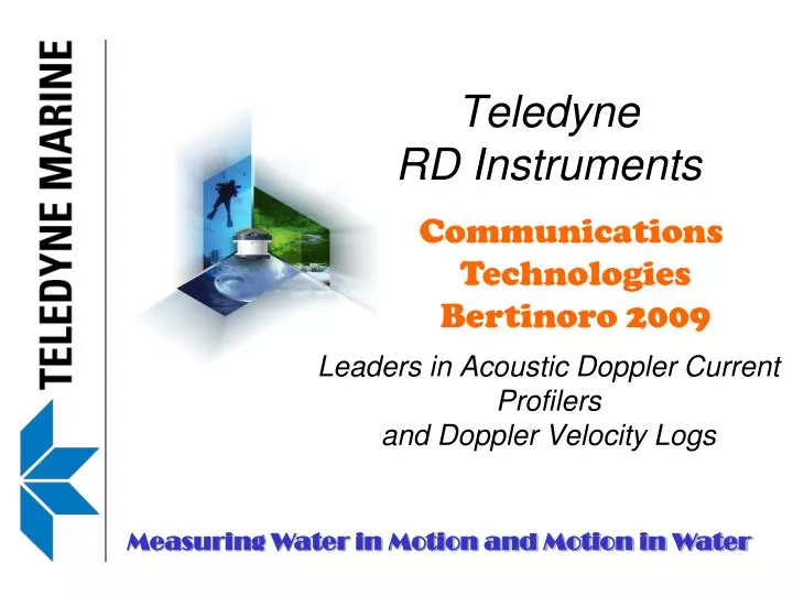
Teledyne RD Instruments Leaders in Acoustic Doppler Current Profilers and Doppler Velocity Logs. Communications Technologies Bertinoro 2009. Measuring Water in Motion and Motion in Water. Measuring Waves Accurately Workhorse Waves Array ADCP. Darryl Symonds

E N D
Teledyne RD InstrumentsLeaders in Acoustic Doppler Current Profilers and Doppler Velocity Logs Communications TechnologiesBertinoro 2009 Measuring Water in Motion and Motion in Water
Measuring Waves Accurately Workhorse Waves Array ADCP Darryl Symonds Director of Marine Measurements Product Lines Teledyne RD Instruments
Waves Measuring Techniques • Pressure Sensor Array • Triplet Processing • Orbital Velocity Array
Pressure Sensor for Waves • Use a single pressure sensor to measure the change in the water surface height; provides non-directional waves data (Wave Height and Period) • Use an array of pressure sensors to measure the change in the water surface height at several locations at once; provides direction waves data (Wave Direction)
Triplet Processing for Waves Uses 3 parameters to provide waves data • Measure changes in the height of the water to provide non-directional waves data (Wave Height and Period) • Measure water velocity to provide directional waves data Techniques PUV – Pressure + U/V Horizontal Velocity Vectors UVW – Vertical Vel + U/V Horizontal Velocity Vectors SUV – Vertical Range + U/V Horizontal Velocity Vectors
Orbital Velocities for Waves • Measures the orbital velocities below the surface at multiple layers to provide 4-20 independent measurements of the orbital velocity created by a passing wave
RDI ADCP Waves Measurements Techniques WH Sentinel Monitor ADCP WH Horizontal ADCP NEMO
RDI Sentinel ADCP Waves Measurements: • Current Profile • Echo Intensity • U/V Velocity • Vert Velocity • Pressure • Surface Track WH Sentinel Monitor ADCP
Triplet Processing – PUV/UVW P P P Pressure = Non Directional Wave Data: Hs, Tp UV Velocity Bin = Directional Wave Data: Dp UVW Velocity Bin = Non Directional and Directional Wave Data: Hs, Tp, Dp
Surface Tracking – 4 Beams 4 Beam Array = Non Directional: Hs, Tp UV Velocity Bin = Directional Wave Data: Dp
Orbital Waves Processing • 4-20 Independent Orbital Fluctuation Sensors • Directional Spectrum with IMLM
Data Provided by the WH Sentinel ADCP Waves System Simultaneous Currents and Waves Current Profile Information • East/North/Vertical Velocity • Error Velocity • Correlation • Echo Intensity • Percent Good
Data Provided by the WH Sentinel ADCP Waves System Simultaneous Currents and Waves Wave Information • Processed Parameters (Height, Period, Direction) • Non Directional Spectra (3 methods; Orbital, Surface Track, and Pressure) • Directional Spectra
Height, Period, Direction, TidesTime Series Significant Wave HEIGHT Peak PERIOD Peak DIRECTION TIDES
Non Directional Spectrum(Wave Height Spectrum) Orbital Array Velocity Surface Tracking Pressure Sensor
Comparing Directional Resolution NarrowBandArray RDI VADCP Array Triplet (PUV)
Summary of the WH Sentinel ADCP Waves System • RDI’s ADCP Wave Array provides several instruments at the same time in one package • current profiling AND • directional wave gauge AND • water level device • Directional Wave Analysis • array type measurement refines direction resolution • Reveals and corrects for bias due to wave-current interaction • 3 independent methods collected for comparison and quality assurance
RDI ADCP Waves Measurements Techniques Measurements: • Horizontal Current Profile • Echo Intensity • U/V Velocity Array • Pressure WH Horizontal ADCP
Orbital Waves Processing • Horizontal ADCP is at a single layer below the surface • Directly measures the entire wave field. • Directional Spectrum with IMLM
Summary of the WH Horizontal ADCP Waves System • Real Time Measurements in Ports, Navigation Channels, and Oil Platforms • Improves Directional Wave Spectra • Improves Long Wave Measurement Performance • Lower system reduced Maintenance Cost
Waves Measuring Setup • Which Processing Method? • What is the Data Collection Interval? • What about Real Time Data Collection?
So which Method to Use? • Data for all 3 methods is collected by the ADCP at the same time. • Each method can be separately processed by the RDI software. • Compare results if all agree then use the Orbital Velocity data • If there are differences verify if the Concerns caused a bias and select the method that does not have bias
Currents Only Ping Setup Single Ping Ensembles 10min Ensemble 10min Ensemble Multiple Ping Ensembles Evenly Spaced in Time 10min Ensemble 10min Ensemble Multiple Ping Burst Ensembles 10min Ensemble 10min Ensemble
Currents Only Ensemble Setup 10 Min 10 Min Burst Ping Ensembles8 Pings/Ens * 6 Ens/Hr = 48 Pings/hr 10 Min 10 Min Burst Ping Ensembles + Burst Ensembles 2 Pings/Ens * 24 Ens/Hr = 48 Pings/Hr 10 Min 10 Min
Waves Sampling Strategies Waves Burst duration is User Selectable, min/typical 20mins 10min Current Ens. 10min Current Ens. Pings for Waves Burst are 2Hz Current Ens. Are User Selectable typical 10mins (TE Cmnd) 10min Current Ens. 10min Current Ens. Pings for Current Ens. within Waves burst are shared with Wave Burst 10minCurrent Ens. 10min Current Ens. Pings for Current Ens. outside Waves burst are at User Selected Interval (TP Cmnd)
Waves Sampling Strategies Wave Burst Wave Burst Waves Burst interval is User Selectable: - min/typical 1 per hour - max 1 per 3 hours 10min Ens. 10min Ens. 10min Ens. 10min Ens. 10min Ens. 10min Ens. 10min Ens. 10min Ens. 10min Ens. 10min Ens. 10min Ens. 10min Ens. 10min Ens. 10min Ens. 10min Ens. 10min Ens. 10min Ens. 10min Ens. 10min Ens. 10min Ens. 10min Ens. 10min Ens. 10min Ens. 10min Ens.
RDI ADCP Real Time Waves Advantages: • Remote Real Time Currents and Waves Processing • Use Orbital Waves or UVW Processing • Allows low data bandwidth applications • Stand alone or integrated NEMO
RDI Integrated Real Time Options • Teledyne Benthos Acoustic Modems • SeaBird Electronics Inductive Modems
RDI WH with Integrated NEMO and Internal/External SBE IMM Integration Setup • Features: • All of the previous • WH Powers NEMO and IMM • Expandable Battery Integration for 30-365 Day Deployments SBE Underwater IMM with coupler and cable mount. WH Sentinel w/RDI NEMO WH External Battery Case
Surface Buoy with Surface Modem Seawater Ground SBE IMM Coupler Insulated mooring cable. Seawater Ground Anchor RDI WH with Internal SBE IMM Integration Setup SBE IMM Coupler RDI WH ADCP RDI WH ADCP with IMM Coupler
RDI WH with Internal SBE IMM Integration Setup • Features: • WH synchronous or asynchronous with IMM • Real time data access • No interruption of asynchronous WH data • Stored data access through IMM 16KByte Loop Recorder • Powered by single WH battery for 1year; deployment duration depends on model and user setup
Inductive Setup Considerations • Mooring Cable Diameter • Support 9.5mm(3/8”) – 19.1mm(3/4“) diameter cables • Coupler spacers supplied to limit cable motion within coupler • Power Consumption • Power consumption for RDI ADCP • Power consumption for IMM data access • Plan for IMM power consumption during other sensor downloads • Data Format • ASCII or Binary data • Complete data or subset
Contacts Main Office: Teledyne RD Instruments, Inc. 14020 Stowe Drive Poway, CA 92064 Main: +1-858-842-2600 www.rdinstruments.com European Office: Teledyne RDI Europe 5 Avenue Hector Pintus La Gaude, France Main: +33-492-110-930 China Office: Teledyne RD Technologies: 1206 Dongfang Road, Pu Dong Shanghai 20122 China Main: +86-215-830-6939 Italy Representative: Gianni Basini & Sandro Giordano Communications Technology Pzza Guidazzi 3 Cesena 97023 Italy +39 0547 646561 gb@comm-tech.com sg@comm-tech.com www.comm-tech.com