Download
1 / 31
350 likes | 617 Views
RS232 to CAN Communication. CSE 470/570 Final Project. Project Description. By: Mike Siemen, Ralph Weber, Adel Abdallah The scope of the project is to transfer data from RS232 to CAN via CML-12C32 Development Board and PC. Introduce CAN and RS232 Interface RS232 and CAN via HC12

E N D
RS232 to CAN Communication CSE 470/570 Final Project
Project Description • By: Mike Siemen, Ralph Weber, Adel Abdallah • The scope of the project is to transfer data from RS232 to CAN via CML-12C32 Development Board and PC. • Introduce CAN and RS232 • Interface RS232 and CAN via HC12 • Lesson Learned • Possible Future Uses of this technology • Total Cost, Manufacturability, Safety
Comparison of CAN and RS232 CAN is a protocol oriented packet RS232 is a character oriented CAN reach speed of 1 Mbps RS232 reach speed of 19.2Kbps CAN uses voltage differential RS232 uses TTL for short distance <3m CAN uses CRC for error detection RS232 uses check sum
Frame Contents SOF Start Of Frame bit RTR Remote Transmission request bit IDE Identifier extension bit DLC Data Length Code CRC Cyclic Redundancy Check ACK ACKnowledge EOF End of Frame
PCA82C250 Transceiver Provides interfacing between a protocol controller and a physical transmission line. It is used in automotive and general industrial applications. It meets the iso11898 standard and the Device Net Specification. Capable of driving a large number of bus nodes, 64 to 100 per network, and bus length of up to about 0.5 to 1 km.
PCA82C250 Transceiver Provides interfacing between a protocol controller and a physical transmission line. It is used in automotive and general industrial applications. It meets the iso11898 standard and the Device Net Specification. Capable of driving a large number of bus nodes,64 to 100 per network, and bus length of up to about 0.5 to 1 km. The bus line must be terminated at both ends by a resistor. In our application we used two 120 ohm resistors, one at each end.
PCA82C250 Transceiver Transceiver Operation Modes Mode 1 – High Speed Mode -The high-speed mode is selected by connecting pin 8 to ground. -Supporting maximum bus speed and/or bus length Mode 2 – Slope Control Mode - Mode 2 is selected by connecting a resistor from pin 8 to ground. -Considered if unshielded bus wires will be used. To lower system cost. -For lower speeds or shorter bus length. Mode 3 – Stand By Mode -If a HIGH level is applied to pin 8, the circuit enters a low current standby mode. -Used when the power consumption needs to be minimized. -In this mode, the transmitter is switched off and the receiver is switched to a low current. -This mode is primarily intended for battery powered applications for example when a vehicle is parked.
ST bit DATA SP bit Project Scope Receive data via RS232 protocol from Computer serial port and store into an array. Build array for 108bits to simulate a CAN frame with buffer (circular buffer) of 14 bytes. Start Array Byte Array Byte Array . . . Array Byte End Array Byte
Project Scope Retrieve data from array and convert to CAN protocol and send on CAN bus. There is 11bits in header and the array is right justified.
HEADER DATA FOOTER Project Scope Receive data via CAN protocol from HC12 board port, store into an array and wait to be read Mask data and slow down the traffic. Array
HEADER ST bit DATA DATA byte FOOTER SP bit Array Byte Array Byte . . . Array Byte Array Byte Project Scope Array Retrieve data from array and convert to RS232 protocol and send on Computer
Configuring the COM Port Configuring the COM port consists of specifying the RS232 serial BAUD rate, the number of data bits, parity, stop bits, and mode of operation. BAUD rate : 19200 bits/sec Data bits range : 8 Parity : None 1 stop bit
CAN Configuration Parameters The CAN configuration parameters consist of propagation delay, phase segment #1 and #2, and the set-jump-window (sjw) parameters. SYNC Parameter: The “SYNC’ field is fixed in hardware and is always one Tq in duration. T_Prop Parameter:The “T_Prop” field represents the total, bi-directional propagation delay between two furthest nodes on a network. The values can range from 1-8. T_SEG_1 Parameter:The “T_SEG_1” parameter determines the amount of time to wait before the hardware attempts to sample the bit. The value can range from 1-8. SJW Parameter: The SJW parameter allows for a CAN node to adjust its sampling point when it determines that the sample point would be too early or too late. The value can range from 1-4
CAN Configuration Parameters Tq Scalar Parameter: Determines the duration of the basic unit of time Tq. The value can range from 1-64 Parameter constraints: “T_SEG_2” must be greater than or equal to two “T_SEG_2” must be greater then or equal to “SJW” “T_SEG_2” must be less then or equal to “T_PROP” + T_SEG_1”
Control Area Network (CAN) Calculation of baudrate and sample point Baudrate The baudrate of the bus can be calculated from: Baudrate = fcrystal / (2*n*(BRP+1)) where n is the number of time quanta for one bit and is defined as : n = SYNCHSEG+TSEG1+TSEG2 BRP is the value of the BaudRate Prescaler.
Control Area Network (CAN) Sample point Quantabeforesample = TSEG1 + 1 Quantaaftersample = TSEG2 Often the sample point is given in percent of the bit time. This is: (TSEG1+1)/(TSEG1+1+TSEG2)
Hardware Used Two HC12 Evaluation board One CANalyzer Two Personal Computers Cable (CAN to CAN) Cable (RS232 to Board) The safety of CAN has been established and is widely used across Automotive and Industry
CML-12C32 Block Diagram Board I/O Overview SCI module CAN module
Interrupt Vector Overview Monitor Interrupt Vector Table
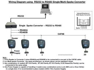
Hardware Connection Overview • Jumper MCU Signal • LED1 PS2 • LED2 PS3 • SW1 PJ6/KWJ6 • SW2 PJ7/KWJ7 Pins 1, 4, and 6 together. TXD 2 RTS 7 RXD 3 CTS 8 N/C 9 GND 5 Hardware connection between CAN and RS232 • 1 GND • 2 CAN-H • 3 CAN-L • 4 +5V
CANalyzer Hardware Questions
References MC68HC12: An Introduction Software and Hardware Interfacing by Han-Way Huang. Haskell Presentation: The Serial Communication Interface (SCI) MC9S12-C32 Haskell Presentation: Controller Area Network (CAN) SJA1000_AN9706 application note 82C250/251 Phillips Data Sheet www.vector_usa.com
Lesson Learned Configuration of CAN was complex to establish The scope of this project should reflect time allowed This project can be used to simulate a CAN frame without uses of a CANalyzer This could be a good tool for Laboratory simulation