Download
1 / 18
200 likes | 504 Views
Electron probe microanalysis E P M A. Diffraction: Electron and X-ray. Related Topics: Diffraction — X-ray and Electron. What’s the point?. There are several other techniques that utilize concepts studied in this class, that may be of use in geologic or material science research:

E N D
Electron probe microanalysis E P M A Diffraction: Electron and X-ray Related Topics: Diffraction — X-ray and Electron
What’s the point? There are several other techniques that utilize concepts studied in this class, that may be of use in geologic or material science research: Diffraction — using either electron or x-ray sources—for determining crystallographic information This can be either macro- or micro-analytical (vis a vis the volumes being studied)
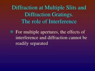
Diffraction—Defined* It is the result of interference (i.e., when waves are superimposed, they may reinforce or cancel each other out) and is most pronounced when the wavelength of the radiation is comparable to the linear dimensions of the obstacle. Diffraction is the spreading of waves around obstacles. It takes place with sound; with electromagnetic radiation, such as light, X-rays, and gamma rays; and with such fast moving particles such as atoms, neutrons, and electrons, which show wavelike properties. * Encyclopedia Britannica, 1974
Coherent Scattering When x-rays interact with matter, the dominant effect is scattering. Considering x-rays as waves we deal with coherent scattering (rather than as particles, where we deal with incoherent scattering). With coherent scattering, photons scatter with no loss of energy, and give rise to scattered radiation of the same wavelength. Classical physical theory says that when electromagnetic radiation (waves) hit electrons, the electron begins to vibrate and become the source of a wave whose phase is determined by that of the incident wave. All the electrons in the material that the wave meets then form a group of coherent sources whose radiation can interfere constructively or destructively. This discussion (above) is taken mainly from Andre Guinier’s X-ray Cryallographic Technology, a 1952 translation of his 1945 classic. Some of the following material is taken from Jim Connolly’s highly recommended UNM CXRD Class Notes.
Constructive Interference The distance between atoms in solids are of the same order size as the x-ray wavelength, and therefore interference phenomena are observed: Instead of feeble energy being distributed throughout space, it is concentrated in certain directions. These concentrations are diffraction patterns whose particular geometries are functions of the positions of the atoms in the material (the crystallography of the solid) and the wavelength of the x-rays. There is another kind of scattering, incoherent (Compton) which is easiest understood in terms of the particle nature of photons: the photon deviates from path and electron takes from it part of its energy. The scattered photon has lost energy (so has a higher wavelength), and there is no relationship between the phases of the 2 waves. There is no interference and of little significance here (though it is for XRF) and we will not consider it further.
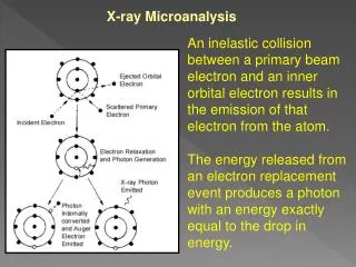
Geometry of Diffraction”“Point Source” The electrons within an atom will scatter x-rays, and because the electrons are “everywhere” within the atom, a secondary point source of scattered radiation appears to originate from the center of the atom (i.e., the nucleus).
Geometry of Diffraction:“Row source” Consider a one-dimensional row of equally spaced atoms. Each atom in the path of the x-ray beam (wave) can be considered to be the center of radiating, spherical wave shells of x-rays. Most scattered x-rays destructively interfere, i.e. cancel out. In certain directions, however, “in phase” scattered x-rays will add together to form a new wave. Since wavelengths of l, 2 l and 3 l will all add to produce a different wavefront, these are called first-, second- and third-order wavefronts.
Diffraction Methods There are several standard experimental techniques used in X-ray diffraction studies: Laue method: a single crystal is held stationary in a beam of polychromatic x-ray radiation. The crystal diffracts the discrete values of l for which planes exist of spacing d and incidence angle q; Rotating-crystal method: a single crystal is rotated about a fixed axis in a beam of monchromatic x-rays. The variation in q brings different atomic planes into position for reflection; Powder (Debye-Scherrer-Hull) method: a finely powdered sample is placed in a holder in a monochromatic x-ray beam, with the angle q gradually changing due synchronous movement of holder and detector. Assuming random orientation of the tiny crystallites, there will be diffraction off of different atomic planes at specific angles.
Our Powder Diffractometer Scintag PAD V (Room 308 Weeks)
Powder Patterns Set up the machine to scan a range of q (here, 4-70°); typical time is ~60 minutes; reconnaissance scans can be much quicker. Then need to process data (model the background, subtract it) and proceed to software identification -->
Powder Patterns -> Identification of natural or synthetic crystalline materials using software (here, MDI’s “Jade” program)
Other Powder XRD Applications • Crystallographic structural analysis and unit-cell calculations • Quantitative determination of amounts of different phases (in multi-phase mixture) by peak-ratio calculations • Quantitative determination of phases by whole-pattern (Rietveld) refinement • Determination of crystallite size from peak broadening • Determination of crystallite shape from peak symmetry • Study of thermal expansion by using in-situ heating stage.
EBSD Electron backscatter diffraction (EBSD) is a technique for determining crystallographic information of submicron regions of flat polished samples. It has made possible studies of microtextures, phase identification (of polymorphs), grain boundary distribution, and deformation microstructures. EBSD is also known by the names backscatter Kikuchi diffraction BKD, or electron backscatter pattern EBSP. The phenomenon has been known since 1928 by Kikuchi, who noted ‘remarkable lines’ resulting from electron diffraction thru a thin mica crystal. Two research groups (in UK) started working on EBSD ~1973, and it has only been commercially available since 1994. In many cases it replaces more time-consuming/difficult TEM or XRD,or possibly electron channeling studies, with the benefit of SEM’s point by point high spatial resolution (<1 mm) together with its ability to scan large areas (~cm). It is relatively inexpensive ($50-100K), in being an add-on attachment to a previously existing SEM.
EBSD Kikuchi recognized the importance of a divergent electron beam being diffracted -- how the spreading of the incident beam (by inelastic scattering in upper surface of sample) Orientation mapping (OIM, orientation imaging microscopy) Phase identification by step by step deduction of pattern point group symmetry, though some problems; other technique is to determine approx value of unit cell volume from measured lattice spacing and interplanar angles, together with EDS, searching a database for possible matches, then match angles
EBSD The sample is tilted steeply (70°, so beam is 20° to sample) which enhances the number of BSEs able to undergo diffraction and escape the surface. The HV electrons are scattered by the electrons of the atoms in the top unit cells of the material, scattering from electrons in crystallographic planes producing intersecting bands imaged by film or a phosphor screen immediately adjacent. The pattern and bands provide information about the crystal structure: Symmetry of crystal lattice Width and intensity of bands are a measure of the plane spacing (and unit volume) Angles between bands are related to the angles between planes in the lattice.
Specimen Prep Specimen prep important: surface must have damaged layer (esp from coarse polishing) removed, e.g. with colloidal silica (which is also chemical etching action); carbon coat must be very very thin (~10Å)
Some References Introduction to X-Ray Powder Diffraction, by Jim Connolly (notes for U NM EPS400-002, epswww.unm.edu/xrd) X-Ray Crystallographic Technology by Andre Guinier (English Translation, 1952) Modern Powder Diffraction by D. L. Bish and J. E. Post (eds), Mineralogical Society of America Reviews in Mineralogy, Vol 20, 1989 Electron Backscatter Diffraction in Materials Science, Edited by Adam J. Schwartz, Mukul Kumar and Brent L. Adams, Kluwer/Plenum, 2000, ISBN 0-306-46487-X (25 articles) An Atlas of Electron Backscatter Diffraction Patterns by D. J. Dingley, K. Baba-Kishi, and V. Randle, 1994, Institute of Physics Publishing.