Download
1 / 41
450 likes | 759 Views
Feedback Control/ Automatic Tracking. This is really stupid. Control System Terminology. Input - Excitation applied to a control system from an external source .(REFERENCE) Output - The response obtained from a system Feedback - The output of a system that is returned to modify the input.

E N D
Feedback Control/ Automatic Tracking This is really stupid
Control System Terminology • Input - Excitation applied to a control system from an external source .(REFERENCE) • Output - The response obtained from a system • Feedback - The output of a system that is returned to modify the input. • Error - The difference between the input and the output.
Air Temp Heater Control Thermostat Temp Wanted
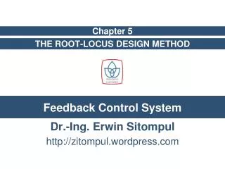
Types of Control Systems • Open-Loop • Simple control system which performs its function without concerns for initial conditions or external inputs. • Must be closely monitored. • Closed-Loop (feedback) • Uses the output of the process to modify the process to produce the desired result. • Continually adjusts the process.
Advantages of a Closed-Loop Feedback System • Increased Accuracy • Increased ability to reproduce output with varied input. • Reduced Sensitivity to Disturbance • Self-correcting minimizes effects of system changes. • Smoothing and Filtering • System induced noise and distortion are reduced. • Increased Bandwidth • Produces sat. response to increased range of input changes.
Major Types of Feedback Used • Position Feedback • Used when the output is a linear distance or angular measurement. • Rate & Acceleration Feedback • Feeds back rate of motion or rate of change of motion (acceleration) • Motion smoothing • Uses a electrical/mechanical device called an accelerometer
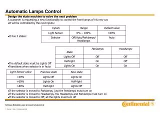
Underdamped Realistically Damped Critically Damped OverDamped
Tracking Systems?? • Determines location or direction of a target on a near-continuous basis. • Ideal system would maintain contact and constantly update the target’s bearing (azimuth), range and elevation. • WHAT IS A TARGET?…
Automatic Tracking Systems (Related to Feedback) • Target Tracking Parameters • Line-of-Sight(LOS) • Tracking Line
Target Tracking Parameters • Azimuth • Elevation • Range • Relative Target Velocity • Target’s motion with respect to the platform’s motion
Tracking Terms Error Line-of-Sight Tracking Line Tracking Element
Angle-Tracking Servo Systems • Five Basic Functions • Sense position error magnitude and direction • Provide position feedback • Provide data smoothing / stabilization • Provide velocity feedback • Provide a power-driving device
Uses of Angle-Tracking Servo Systems • Monotrack fire control radars • Homing missiles • Acoustic homing torpedoes • Aviation fire control tracking systems
Methods of tracking • Sequential Lobing • Conical scan • Conical scan on receive only (COSRO) • Monopulse
Basic Principle: Target energy return is strongest on the axis of the beam, diminishes further from the axis. Methods of Tracking: * Sequential Lobing * Conical Scan * COSRO * Monopulse axis Position Error Magnitude & Direction
L R L R R L * Simplest Method * Multiple Beams * Compare Returns * Relatively Slow * Still used by some countries Antenna looking left of target Antenna Pointing directly at target Antenna looking right of target Return Signals form Two Beams Sequential Lobing
Conical Scanning Lobe Of Energy Pattern of scanning * Rotates a beam in a circle producing a cone of energy. *Rotate the feed horn in a small circle around the axis of the fixed parabolic antenna. Antenna
Locus of Beam Centers Antenna Axis Equal Amplitude Sensor Return Signal Beam Pulse Return Amplitude Time Target Position is in the Center of the Conical Scan (On Antenna Axis) Determining Tracking Error Using Conical Scan
Locus of Beam Centers Antenna Axis Varying Amplitude Sensor Return Signal Beam Pulse Return Amplitude Time Target Position Off the Center of the Antenna Axis Determining Tracking Error Using Conical Scan
*Transmits pulses on axis of the antenna. * Measured strength of return around the axis of the antenna. * Positions the antenna based on the return. DECEPTIVE: Looks like non- Scanning pulse radar Antenna COSROConical Scan on Receive Only
Monopulse • Developed to overcome tracking errors involved with conical scanning and sequential lobing. • Two or more beams are transmitted simultaneously and an amplitude comparison is mode between the returns. • One reflector but uses two or more feed horns. • Each simultaneous beam can be identified by tagging it with some type of information such as slight polarization. • Usually 4 beams: 2 for elevation and 2 for azimuth • Very complex and expensive.
Providing a Stable Tracking System • All tracking systems require some stabilization. • Three classes of stabilization for Tracking Systems • Unstabilized - Not stabilized in any axis • Partially Stabilized - Subsystem is stabilized on one axis. • Fully Stabilized - Completely free of any rotational disturbances. • Gyroscopes provide the stable reference.
Basic Gyroscope Principles • The gyro spins at a very high velocity, and its spin axis remains aligned with terrestrial meridians. • Inertia • Rigidity (A gyro will remain at a fixed orientation in space if no force is applied to it) • A gimbaled gyro makes a good reference to cancel out platform role, pitch and yaw. (On a ship!)
Basic Gyroscope Principles • Precession • A gyro’s spin axis has a tendency to turn at right angles to the direction of the force applied to it. • Used to convert torque required to move the gyro is converted into a means of controlling system gain. • The gyro has three axes: • spin axis • torque axis • precession axis
Gyroscope Theory Accelerometers!!!
Now, put ‘em together!!!! • Range Tracking • Angle Tracking One dead duck…………………..
Question 1 • What does COSRO stand for?
Question 2 • Damping is: A. A type of horizontal polarization. B. The process by which your weapon system/tracking system turns to a new contact without overshooting the target. • Transmission from a Phased Array Radar. • Getting really wet.
Question 3 • Give an example of an Open Loop Control System. Not a stovetop burner
Question 4 • Give an example of an Closed Loop Control System.
Question 5 • In order to stabilize your weapons launcher or tracking system, the system must be able to receive input from what piece of equipment? • BSY-1 • The Captain • The Gyroscope • The SPY-1D
Extra Credit How many Nuclear Powered ships does the Navy currently own and operate?