Download
1 / 19
190 likes | 193 Views
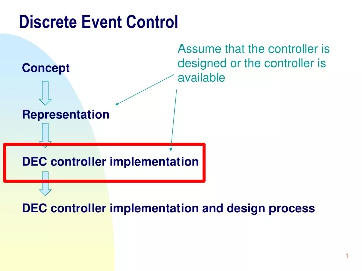
Discrete Event Control. Assume that the controller is designed or the controller is available. Concept Representation DEC controller implementation DEC controller implementation and design process. Application problem. State diagram. Electric Ladder Logic Diagram (ELLD).

E N D
Discrete Event Control Assume that the controller is designed or the controller is available Concept Representation DEC controller implementation DEC controller implementation and design process
Application problem State diagram Electric Ladder Logic Diagram (ELLD) DEC controller implementation Logic equation Software Ladder Logic Diagram (SLLD) Hard wired systems inflexible software systems computer-based system
DEC controller implementation Electric Ladder Logic Systems or Diagrams Software Ladder Logic Systems or Diagrams Particular PLC implementation
Electrical Ladder Logic Diagrams Using switch to control a light L: L=1 (light on) L=0 (light off) S: S=1 (switch on) S=0 (switch off) Electric Ladder Logical Diagram is as follow (Fig.1): Traditional representation of discrete even controller Figure 1
Electrical Ladder Logic Diagrams (ELLD) The structure of ELLD is: - left rail with power -> power rail - right rail with neutral -> neutral rail - one path called “rung” It is clear with the notation on Fig.1, • L=1 if and only if S=1, and • L=0 if and only if S=0 This ELLD is a representation of the Boolean logic equation L=S
Electrical Ladder Logic Diagrams • Fig. 2 represents: • L1=S1+S2 (Rung 1) • L2=S2S3 (Rung 2) • Boolean Logic equation Fig. 2 shows a multiple rungs (two rungs). Problem: - Two lights, L1 and L2. - Three switches, S1, S2, S3 • Narrative description: • When S1 or S2 is on, L1 is on • When both S2 and S3 are on, L2 is on. Figure 2 ELLD No cross-link between any two rungs
This design cannot achieve the requirement (2) Electrical Ladder Logic Diagrams From a design problem point of view, the requirement is: Two lights: (1) L1 is on but L2 is off, (2) L2 is on but L1 is off, and (3) both L1 and L2 are on • Narrative description: • When S1 or S2 is on, L1 is on • When both S2 and S3 are on, L2 is on and L1 is on. • When S1, S2, S3 are all on, L1 and L2 are on. Figure 2 • L1=S1+S2 (Rung 1) • L2=S2S3 (Rung 2) • Boolean Logic equation ELLD
Electrical Ladder Logic Diagrams Control Relays: Instead of using one switch to control one light or object, a more general component for hardwired control implementation is a control relay, see Fig. 3. Features of the control relay are: • Coil with many normally closed (n.c.) contacts as well as normally open contacts (n.o.). • If there is a current in the coil, the coil is energized, then n.c. contact will open and n.o. contact will close. Figure 3 • Benefits of CR: • More rich set of means to build a controller especially with n.c. contacts. • Resolution to the problem with the momentary switch. • Simultaneous control of multiple “switches” (contacts mimic switches)
Electrical Ladder Logic Diagrams CR represents the coil with a circle on as well as contacts with their corresponding drawings in ELLD n.o. contact n.c. contact
Electrical Ladder Logic Diagrams • Narrative description of the controller: • when S is open, L1 is off, L2 is on. • when S is closed, L1 is on, L2 is off. From a design problem point of view, the requirement is: • L1 is on but L2 is off, • L2 is on but L1 is off Figure 4 Make reference to a particular CR CR: coil CR: n.o. contact CR: n.c. contact ELLD
Electrical Ladder Logic Diagrams • The Boolean logic equations for the rungs in the ladder diagram (Figure 4) are: • Rung 1: CR=S • Rung 2: L1=CR • Rung 3: L2=CR • CR represents coil as well as contacts. • Combining the equations for the rungs yields • L1=S • L2=S ELLD Boolean logic equations
This design cannot achieve the requirement (2) Electrical Ladder Logic Diagrams Design requirement: • L1 is on but L2 is off, • L2 is on but L1 is off, and • both L1 and L2 are on Design requirement: • L1 is on but L2 is off, • L2 is on but L1 is off Figure 4 Figure 2 ELLD L1=S1+S2 L2=S2S3 L1=S L2=S Boolean logic equations
Electrical Ladder Logic Diagrams Example 1: one motor with two pushbuttons: start and stop State variables: PB1 (for start), PB2 (for stop), M (for motor) Figure 5 (control relays are used) From a design problem point of view, the requirement is: Start motor to run and stop motor running. Figure 5 Pushbuttons are a kind of momentary switch. ELLD
Electrical Ladder Logic Diagrams From Figure 5, we know: PB1 is on --> CR1 energized, n.o. contact 1 is closed --> M=1 PB2 is on --> CR2 energized, n.c. contact 2 is open --> M=0 Rung 1: CR1=(PB1+CR1) CR2 Rung 2: CR2=(PB2) Rung 3: M=CR1 CR2 ELLD Boolean logic equations
Electrical Ladder Logic Diagrams Boolean logic equations Finally, M=(PB1+CR1)(PB2)(PB2)=(PB1+CR1)PB2 Contact CR1 may be omitted here if the switch here is “permanent”. When the switch is momentary (i.e., the switch will momentarily close and then be back to unclose state), we need CR1. This is because otherwise, there will be no power on rung 1 shortly after PB1 is pressed. The role of CR1 is to keep the power through on the rung even though PB1 is shortly back to unclose state. Such a role of CR1 is called “latching”.
Electrical Ladder Logic Diagrams Boolean logic equations derived from the ELLD Finally, M=(PB1+CR1)(PB2)(PB2)=(PB1+CR1)PB2 Boolean logic equations derived from the state diagram Remark: The difference implies a shortcoming with the state diagram / logical question approach, that is, they may miss the capturing of the latching function. M+=(PB1+M)PB2 PB1=1 M=0 M=1 PB2=1
Examine for on (or contact) condition Contact, Not-contact Examine for off (or not-contact) condition Software Ladder Logic Diagrams (SLLD) General idea: True (on, 1) or false (off, 0) Electric Ladder Logic Diagram • Switch • Button • Coil • Relay True (on, 1) or false (off, 0)
Software Ladder Logic Diagrams Examine for on Examine for off Viewpoint An input device Remark: Both views are accepted, and their results are different but their conclusions are the same
Software Ladder Logic Diagrams On is true Examine for on Equivalence Off is false Examine for off Metaphor: Chris is a good person == Chris is not a bad person