Download
1 / 11
110 likes | 296 Views
GTK - TDC analysis. Lukas Perktold 24 th February 2010. Progress. Layout vs Schematic ► Parasitic extraction Corner Simulation ? check Loop Dynamics. LVS. Layout vs Schematic - Match. layout not strictly hierarchically for large designs rather time consuming (~3h per run)

E N D
GTK - TDC analysis Lukas Perktold 24th February 2010
Progress Layout vs Schematic ► Parasitic extraction • Corner Simulation ? check Loop Dynamics
LVS • Layout vs Schematic - Match • layout not strictly hierarchically • for large designs rather time consuming (~3h per run) • running LVS for DLL and EndOfColumn
Parasitics • two suspicious nodes • both use weak drivers to drive load A) From Delay Line to Phase Detector B) Driver to drive Hit Registers green: strong drivers (factor 8x) blue: “analog” clock signal (550 mV – 1.2 V)
Layout - EndOfColumn <0> <0> <1> <1> <2> <2> <3> <3> Delay Line Hit Registers Coarse Counter + Hit Registers Coarse Counter + Hit Registers <4> <4> <5> <5> <6> <6> <7> <7> <8> <8> Delay Line Delay Line PD, CP, LF & Logic PD, CP, LF & Logic
DL to PD - Parasitics • Metal 2 wire • width = 0.28 um • length ~ 250 um • some minimum distance neighbor • Resistance ~ 50 Ohm • Capacitance ~ 100 fF • time constant: tau = 5 ps • cannot simulate whole circuit with parasitic components • some nodes cannot be extracted -> Design Kit version ?!? (using old version)
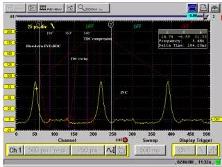
Corners DL to PD – Simulation • yellow: ideal freq = 320 MHz D = 0.497 tr = 106 ps tf = 45 ps red: with parasitics freq = 320 MHz D = 0.493 tr = 207 ps tf = 118.7 ps VDD = 1.2 no strong influence
Corners Hit Registers Driver • extractions needs to be done – currently under investigation • Metal 4 (MQ) wire • width = 0.4 um • length ~ 300 um • no neighbors • Resistance ~ 50 Ohm • Capacitance ~ 100 fF • time constant: tau = 5 ps - 60 fF decoupled capacitance - no Resistors extracted?
Corners Corners • have very weak clock • dummies at input reconstruct “nice” clock • corners might cause the clock to degrade – needs to be investigated
Outline • complete parasitic extraction • investigate influence of corners • use more intensively input from measurements to confine source of problems - Weak performance (e.g. INL) of the TDC for rising edges - Zero dies out for higher frequencies - Under certain conditions loop doesn’t lock - compare RFN settling values - Measurement results of new chip • Need to decide on Design-Kit / Cadence version for the next tape out ...