Download

1 / 19
190 likes | 191 Views
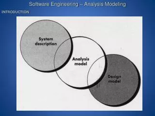
This presentation focuses on a general methodology for multifunctional modeling, analysis, and solution in engineering science, with applications in various disciplines and domains. It demonstrates the formulation for scalar- and vector-field applications and highlights the benefits of collaborative interface treatment. The methodology enables the synthesis of diverse models and provides rapid, robust solutions with multi-fidelity modeling and multiple methods.

E N D
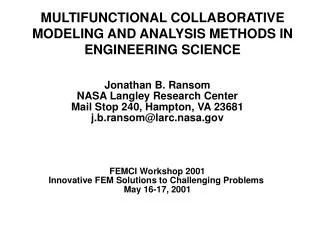
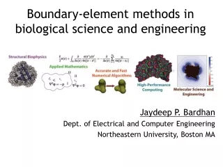
MULTIFUNCTIONAL COLLABORATIVE MODELING AND ANALYSIS METHODS IN ENGINEERING SCIENCE Jonathan B. Ransom NASA Langley Research Center Mail Stop 240, Hampton, VA 23681 j.b.ransom@larc.nasa.gov FEMCI Workshop 2001 Innovative FEM Solutions to Challenging Problems May 16-17, 2001
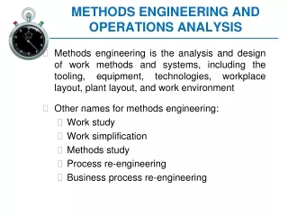
Multi-fidelity FE Modeling • Requires months to model • Changes expensive, • time consuming and error prone • Model often tied to discipline CONVENTIONAL MODELING AND ANALYSIS OF COMPLEX SYSTEMS Multifunctional Collaborative Methodology • Multi-fidelity • Multiple Methods • Multiple Disciplines
OBJECTIVES • Present general methodology providing capability for multifunctional modeling, analysis and solution • Identify computational aspects and related algorithmic issues for this methodology • Demonstrate the formulation to scalar- and vector-field applications in engineering science
Example-Previous interface technology demonstrated collaborative method for homogeneous FE modeling applied to solid mechanics KEY TERMINOLOGY • Multifunctional - Computational methodologies for rapid, robust solutions featuring multi-fidelity modeling and multiple methods • Collaborative - Mechanism by which two or more physical domains or methods are integrated/interfaced • Engineering science -Broad spectrum of engineering (science, mathematics, numerical analysis) • Homogeneous modeling -Same spatial modeling approach among subdomains • Heterogeneous modeling -Different spatial modeling approaches among subdomains
FEM Model Interfacing Multiple Method Interfacing Non-FEM Model Interfacing Multiple Discipline Interfacing Materials Structures Electromagnetics Acoustics Flight Systems Aerodynamics Capability which Enables the Synthesis of Diverse Models MULTIFUNCTIONAL METHODOLOGY Multifunctional Methods Concept and General Formulation Homogeneous Modeling Heterogeneous Modeling Multiple methods Multi-fidelity Multiple-domain Multiple disciplines
OUTLINE • Multifunctional Formulation • Basic assumption • Method of weighted residuals for MFC approach • Collaborative interface treatment • General system of equations • Selected Applications • Concluding Remarks
MULTIFUNCTIONAL FORMULATION-BASIC ASSUMPTION- Deformation, v, along the interface connecting the substructures, i, may be expressed as: v = TqI • where: • Tis an interpolation matrix formed using cubic splines • qIis a vector of interface degrees of freedom
Governing equation within the domain Compatibility constraint for primary variable on interface boundary Compatibility constraint for secondary variable on interface boundary MULTIFUNCTIONAL FORMULATION- METHOD OF WEIGHTED RESIDUALS - Define: where the orthogonalized residuals associated with:
For weight functions: FE domains: FD domains : Assume for each interface i: substituted into: MULTIFUNCTIONAL FORMULATION- COLLABORATIVE INTERFACE TREATMENT -
. For vector-fields . where are dependent on fluid mechanics formulation and is discipline-specific Matrix characteristics: • Sparse • Non-positive definite • May be unsymmetric MULTIFUNCTIONAL FORMULATION- GENERAL SYSTEM OF EQUATIONS - General matrix form for multifunctional collaborative approach For scalar-fields
APPLICATIONS • Patch Test Example Problems • Torsion of Prismatic Bar • Heat Conduction Problem • Potential Flow Problem • Plane Stress Problem • Plane Flow Problem • Boeing Crown Panel • Douglas Stub-Box
0.35 0.30 0.25 0.20 0.15 0.10 0.05 0.00 0.35 0.30 0.25 0.20 0.15 0.10 0.05 0.00 0.35 0.30 0.25 0.20 0.15 0.10 0.05 0.00 Interface kT(x,0) Q kT(x,0) Q kT(x,0) Q 0.0 0.2 0.4 0.6 0.8 1.0 0.0 0.2 0.4 0.6 0.8 1.0 0.0 0.2 0.4 0.6 0.8 1.0 x x x y x HEAT CONDUCTION PROBLEM Square Plate FE/FE Modeling FD/FD Modeling FD/FE Modeling
PLANE STRESS PROBLEM Plate with Central Cutout E=10,000 ksi ν=0.3 h=0.1 in. Two Configurations: Infinite plate: 2a/R0 = 40 2b/R0 = 20 Geometric Configuration Finite-width plate: 2a/R0 = 4 2b/R0 = 2
D C B A Along line CD Along line AB Interface ; ; STRESS RESULTANT DISTRIBUTION FOR FINITE-WIDTH PLATE Spatial Modeling Stress Resultant Contours D C B A
Crown Panel Geometry J-Frame Gap Hat Stiffener Mouse Hole Area 64 in. 68 in. COLLABORATIVE METHODOLOGY DEMONSTRATED ON BOEING CROWN PANEL Radius = 122 in.
Gap Mouse Hole Area COLLABORATIVE METHODOLOGY DEMONSTRATED ON BOEING CROWN PANEL Nested Finite Element Models Combined Finite Element Model Deformation Contour Hoop Stress Contour
APPLICATION OF COLLABORATIVE METHODOLOGY IN NONLINEAR ANALYSIS OF WING STUB BOX Tip load Extension structure Gages C/D 160 160 Failure line Gage B Gage A Gage A 120 120 Gage A x Tip load Tip load x x Test 80 Test x 80 x Gage C (kips) (kips) x x C Gage A Gage D Gage B Analysis 40 40 Analysis D Gage C Gage A Gage D Gage B 0 0 -8000 -6000 -4000 -2000 0 2000 -8000 -6000 -4000 -2000 0 2000 Axial Strain (microstrains) Circumferential Strain (microstrains) Composite wing stub box Local Model of Nonlinear Region Hydraulic jack Experimental Setup Deformed Shape Access Door Cutout Nonlinearly Deformed Unstiffened Bay
SUMMARY • Results presented for patch test, scalar-field, and vector-field problems • Results for all problems and multifunctional approaches in overall good agreement • Finite element solutions more accurate than finite difference solutions for discretizations considered • Results with heterogeneous modeling not as accurate as homogeneous modeling
CONCLUSIONS • Multifunctional collaborative methodologies and analysis procedures formulated and placed on solid mathematical foundation • Scalar-field and vector-field problems • Homogeneous and heterogeneous modeling • Collaborative role of modeling approaches has been illustrated • Capabilities demonstrated on benchmark problems and large scale applications • Computational challenges overcome • Application of FD method limits general use