Download
1 / 8
300 likes | 1.17k Views
Synchronous Reactance. The value of X S can be determined by measurements of the open-circuit and short-circuit tests Test are conducted under an unsaturated core condition

E N D
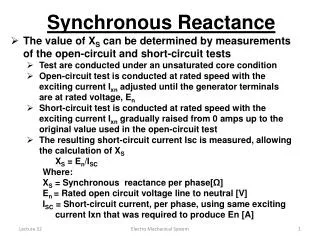
Synchronous Reactance • The value of XS can be determined by measurements of the open-circuit and short-circuit tests • Test are conducted under an unsaturated core condition • Open-circuit test is conducted at rated speed with the exciting current Ixn adjusted until the generator terminals are at rated voltage, En • Short-circuit test is conducted at rated speed with the exciting current Ixn gradually raised from 0 amps up to the original value used in the open-circuit test • The resulting short-circuit current Isc is measured, allowing the calculation of XS • XS = En/ISC • Where: • XS = Synchronous reactance per phase[Ω] • En = Rated open circuit voltage line to neutral [V] • ISC = Short-circuit current, per phase, using same exciting current Ixn that was required to produce En [A] Electro Mechanical System
Example • A 3-phase synchronous generator produces an open-circuit line voltage of 6928 V when the dc exciting current is 50 A. The ac terminals are then short-circuited under the same excitation, the three line currents are 800 A • Calculate the per-phase synchronous reactance • Calculate the resulting terminal voltage if 12-ohm resistors are connected in wye across the terminals • Solution: • Line to neutral induced voltage is • EO = EL /√3 = 6928 / √3 = 4000V • Neglecting resistance, synchronous reactance per phase is • XS = En/ISC = 4000/800 = 5Ω Electro Mechanical System
Example • Equivalent circuit per phase is shown • The impedance can be calculated as: • The current is : • I = EO / Z = 4000 / 13 = 308 A • Voltage across the resistor is: • E = I R = 308 x 12 = 3696 V • The line voltage under load is: • EL = √3 E = √3 x 3696 = 6402 V Electro Mechanical System
Synchronous generator under load • Behavior of a synchronous generator depends upon the type of load it has to supply. Loads, can be of two basic categories: • Isolated loads, supplied by a single generator 2) The infinite bus • For isolated loads; Consider a generator that supplies power to a load with a lagging pf. For phasor diagram, we list the following facts: • Current I lags behind terminal voltage E by an angle . • Cosine = power factor of the load. • Voltage Ex across the synchronous reactance leads current I by 90°. Given by the expression Ex = jIXs. • Voltage Eo generated by the flux is equal to the phasor sum of E + Es. • Both Eo and Ex are voltages that exist inside the synchronous generator windings and cannot be measured directly. • Flux is that produced by the dc exciting current Ix • Phasor diagram shows Eo leads E by δ degrees & Eo is greater than E Electro Mechanical System
Synchronous generator under load • If the load is capacitive, current I leads the terminal voltage by . • In the new phasor diagram, the voltage Ex across the synchronous reactance is still 90° ahead of the current. • Eo is again equal to the phasor sum of E and Ex. • The terminal voltage is now greater than the induced voltage Eo, which is a very surprising result. • The inductive reactance Xs enters into partial resonance with the capacitive reactance of the load. • It may appear we are getting something for nothing, the higher terminal voltage does not yield any more power. • If the load is entirely capacitive, a very high terminal voltage can be produced with a small exciting current. Electro Mechanical System
Example • A 36 MVA, 20.8 kV, 3-phase alternator has a synchronous reactance of 9Ω and a nominal current of 1 kA. The no-load saturation curve giving the relationship betweenEOand Ix is given. If the excitation is adjusted so that the terminal voltage remains fixed at 21 kV, calculate the exciting current required and draw the phasor diagram for the following conditions: • No-load • Resistive load of 36 MW • Capacitive load of 12 Mvar We shall immediately simplify the circuit to show only one phase. The line-to-neutral terminal voltage for all cases is fixed at E = 20.8/√3 = 12 kV a) At no-load there is no voltage drop in the synchronous reactance; consequently, Eo = E= 12 kV Excitation current : Ix = 100 A Electro Mechanical System
Example b) With a resistive load of 36 MW: The power per phase is: P = 36/3 = 12 MW The full-load line current is: I = P/E = 12 x 106/12 000 = 1000 A = 1kA Current is in phase with the terminal voltage. The voltage across Xs is Ex = jIXs =j1000 x 9 = 9 kV 90° This voltage is 90° ahead of I. The voltage E0 generated by Ix is equal to the phasor sum of E and Ex. Referring to the phasor diagram, its value is The required exciting current is: Ix = 200 A Electro Mechanical System
Example c) With a capacitive load of 12 Mvar: The reactive power per phase is: Q = 12/3 = 4 Mvar I =Q/E = 4 X 10⁶/12 000. = 333 A The voltage across Xs is : Ex = jIXs = j333 x 9 = 3 kV 90o As before Ex leads I by 90° The voltage EO generated by Ix is equal to the phasor sum of E and Ex. Eo = E + Ex = 12 + (-3) = 9kV The corresponding exciting current is : Ix = 70 A Note that EO is again less than the terminal voltage E. Electro Mechanical System