Download
1 / 37
410 likes | 724 Views
Synchronous Induction. An alternator http://www.physclips.unsw.edu.au/jw/electricmotors.html#generators. An alternator.

E N D
Synchronous Induction An alternator http://www.physclips.unsw.edu.au/jw/electricmotors.html#generators
An alternator • In the next animation, the two brushes contact two continuous rings, so the two external terminals are always connected to the same ends of the coil. The result is the unrectified, sinusoidal emf given by NBAw sin wt, which is shown in the next animation
An alternator • This is an AC generator. The advantages of AC and DC generators are compared in a section below. We saw above that a DC motor is also a DC generator. Similarly, an alternator is also an AC motor. However, it is a rather inflexible one. (See How real electric motors work for more details.)
Back emf • Now, as the first two animations show, DC motors and generators may be the same thing. For example, the motors of trains become generators when the train is slowing down: they convert kinetic energy into electrical energy and put power back into the grid. Recently, a few manufacturers have begun making cars rationally. In such cars, the electric motors used to drive the car are also used to charge the batteries when the car is stopped - it is called regenerative braking.
Back emf • So here is an interesting corollary. Every motor is a generator. This is true, in a sense, even when it functions as a motor. The emf that a motor generates is called the back emf
Back emf • The back emf increases with the speed, because of Faraday's law. So, if the motor has no load, it turns very quickly and speeds up until the back emf, plus the voltage drop due to losses, equal the supply voltage
Back emf • The back emf can be thought of as a 'regulator': it stops the motor turning too quickly. When the motor is loaded, then the phase of the voltage becomes closer to that of the current (it starts to look resistive) and this apparent resistance gives a voltage. So the back emf required is smaller, and the motor turns more slowly. (To add the back emf, which is inductive, to the resistive component, you need to add voltages that are out of phase. See AC circuits.)
AC motors • With AC currents, we can reverse field directions without having to use brushes. This is good news, because we can avoid the arcing, the ozone production and the ohmic loss of energy that brushes can entail. Further, because brushes make contact between moving surfaces, they wear out.
AC motors • The first thing to do in an AC motor is to create a rotating field. 'Ordinary' AC from a 2 or 3 pin socket is single phase AC--it has a single sinusoidal potential difference generated between only two wires--the active and neutral. (Note that the Earth wire doesn't carry a current except in the event of electrical faults.)
AC motors • With single phase AC, one can produce a rotating field by generating two currents that are out of phase using for example a capacitor. In the example shown, the two currents are 90¡ out of phase, so the vertical component of the magnetic field is sinusoidal, while the horizontal is cosinosoidal, as shown. This gives a field rotating counterclockwise.
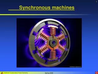
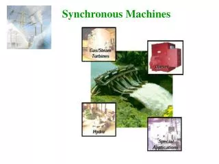
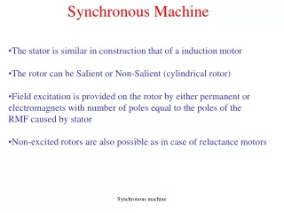
Synchronous Machines A synchronous machine is an ac rotating machine whose speed under steady state condition is proportional to the frequency of the current in its armature. The magnetic field created by the armature currents rotates at the same speed as that created by the field current on the rotor, which is rotating at the synchronous speed, and a steady torque results.
Synchronous Machines Synchronous machines are commonly used as generators especially for large power systems, such as turbine generators and hydroelectric generators in the grid power supply. Because the rotor speed is proportional to the frequency of excitation, synchronous motors can be used in situations where constant speed drive is required.
Synchronous Machines Since the reactive power generated by a synchronous machine can be adjusted by controlling the magnitude of the rotor field current, unloaded synchronous machines are also often installed in power systems solely for power factor correction or for control of reactive kVA flow. Such machines, known as synchronous condensers, may be more economical in the large sizes than static capacitors.
Synchronous Machine Structures The armature winding of a conventional synchronous machine is almost invariably on the stator and is usually a three phase winding. The field winding is usually on the rotor and excited by dc current, or permanent magnets. The dc power supply required for excitation usually is supplied through a dc generator known as exciter, which is often mounted on the same shaft as the synchronous machine. Various excitation systems using ac exciter and solid state rectifiers are used with large turbine generators.
Rotor Types • Generally, round rotor structure is used for high speed synchronous machines, such as steam turbine generators, • while salient pole structure is used for low speed applications, such as hydroelectric generators.
Electrical Angle A great many synchronous machines have more than two poles. As a specific example, we consider a four pole machine. As the rotor rotates for one revolution (qm=2), the induced emf varies for two cycles (q = 4), and hence = 2 m
Electrical Angle For a general case, if a machine has Ppoles, the relationship between the electrical and mechanical units of an angle can be readily deduced as: Taking derivatives on the both side of the above equation, we obtain
Rotating mmf The above diagram plots the resultant mmf F1 at two specific time instants: t=0 and t=p/2w. It can be readily observed that F1 is a rotating mmf in the +direction (a b c) with a constant magnitude 3Fm/2. The speed of this rotating mmf can be calculated as:
Synchronous M/C Generator Motor
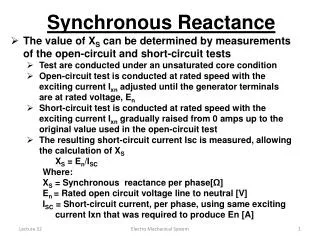
Open & Short circuit Tests Short Circuit Test Open Circuit Test