Download
1 / 35
400 likes | 836 Views
Chapter 6-1 ALU, Adder and Subtractor. Simple ALU Adder Subtract o r Next Lecture Multiplier Divider Floating Point Numbers. Simple ALU (arithmetic logic unit). operation. op. a. b. res. result. operation. a. ALU. 32. result. 32. b. 32.

E N D
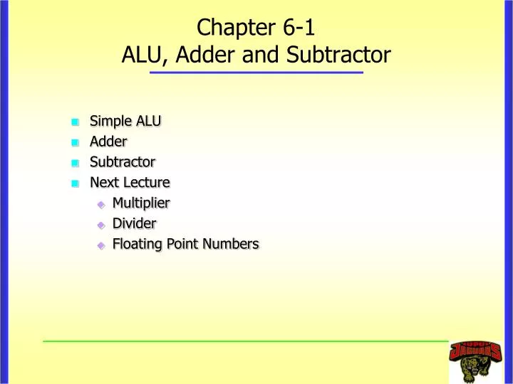
Chapter 6-1ALU, Adder and Subtractor • Simple ALU • Adder • Subtractor • Next Lecture • Multiplier • Divider • Floating Point Numbers
Simple ALU (arithmetic logic unit) operation op a b res result operation a ALU 32 result 32 b 32 • Let's build an ALU to support the “and”and “or”instructions • Just build a 1-bit ALU, and use 32 of them (bit-slice) a b
Review: The Multiplexer • Selects one of the inputs to be the output, based on a control input • Lets build our ALU using a MUX: S note: we call this a 2-to-1 mux A C 0 B 1
AND and OR ALU Operation 0 Result A 1 B
Subtraction Support C a r r y I n O p e r a t i o n a 0 C a r r y I n R e s u l t 0 A L U 0 b 0 C a r r y O u t a 1 C a r r y I n R e s u l t 1 A L U 1 B i n v e r t b 1 C a r r y O u t a 2 C a r r y I n R e s u l t 2 A L U 2 b 2 C a r r y O u t a 3 1 C a r r y I n R e s u l t 3 1 A L U 3 1 b 3 1 • Two's complement approach: just negate b and add 1 using XOR gates sub
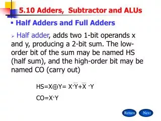
Full Adder • The K-maps for • Ci+1: • Si: BiCi Ai 0 0 1 0 0 1 1 1 BiCi Ai 0 1 0 1 1 0 1 0 Truth Table Ci A + Sum B Ci+1
Full Adder (cont.) BiCi Ai 0 0 1 0 0 1 1 1 BiCi Ai 0 1 0 1 1 0 1 0 • Boolean equations: • Ci+1= AiBi + AiCi + BiCi = AiBi + (Ai+Bi)Ci • Si= AiBi’ Ci’ + Ai’Bi’Ci + Ai’BiCi’ + AiBiCi= Ai Bi Ci • Ci+1= AiBi + AiBi’Ci + Ai’BiCi = AiBi + (AiBi’ + Ai’Bi)Ci= AiBi + (AiBi)Ci
Full Adder using 2 Half Adders Ai Bi Si Ci+1 Ci Ci+1 = AiBi + (Ai Bi)Ci Si= Ai Bi Ci
1-bit Full Adder Ci Ai Sum + Bi Cout Ai Sum Bi Ci Cout
4-bit Ripple-Carry Adder 1 1 0 1 0 1 1 0 1 +1 1 0 1 ---------- 1 0 1 0 C4 C3 C2 C1 C0 A3 A2 A1 A0 +B3 B2 B1 B0 -------------- S3 S2 S1 S0
4-bit Ripple Adder A Full Adder Ai S Bi Cout C3 C2 C1 C0A3 A2 A1 A0 +B3 B2 B1 B0 -------------- S3 S2 S1 S0 Ci Cout A3 B3 A2 B2 A1 B1 A0 B0 Cout C0 carry3 carry2 carry1 S3 S2 S1 S0 Critical Path = DXOR+4*(DAND+DOR) for 4-bit ripple adder (9 gate levels) For an N-bit ripple carry adder Critical Path Delay 2(N-1)+3 = (2N+1) Gate delays
Design of Fast Adders • n-bit ripple carry adder may have too much delay in developing its outputs, s0 through sn-1 and cn • The delay through a network of logic gates depends on • Integrated circuit fabrication technology • The number of gates in the path(s) from input(s) to output(s) • The delay incurred with any combinational logic network constructed from gates in a given technology can be determined by adding up the amount of logic gate delays along the longest path through the network • We require that an arithmetic operation is completed in one clock cycle • Example: for a processor operating at 100Mhz, an addition must complete in 10ns
Design of Fast Adders (cont.) A B A B A B n - 1 n - 1 1 1 0 0 c c n - 1 1 c c F A F A F A n 0 s s s n - 1 1 0 Most significant bit Least significant bit (MSB) position (LSB) position • Suppose that the delay from from ci to ci+1 of any adder block is 1ns • an n-bit addition can be performed in the time it takes the carry signal to reach cn-1 position plus the time it takes to develop sn-1 • A 32-bit addition may approximately take 32 ns • Two approaches can be used to reduce this delay • Faster circuit technology • Make Si and Ci+1independent of Ci
Design of Fast Adders (cont.) • How to make Si and Ci+1independent of Ci • Motivation: • If we didn't know the value of carry-in, what could we do? • Ci+1= AiBi + AiCi + BiCi = AiBi+ (Ai+Bi)Ci • When do we always generate a carry? Gi = AiBi • When do we propagate the carry? Pi = Ai+Bi
Express Sum and Carry as a function of P, G • Full adder expressions • Ci+1= AiBi+AiCi+BiCi = AiBi+(Ai+Bi)Ci = AiBi+(AiBi)Ci • Si= AiBi Ci • Gi = AiBi • Pi = Ai+Bi = AiBi • Ci+1(G,P)=Gi+PiCi (do you still see ripple here?) • Si(G,P)= PiCi (no ripple) Independent of Ci
Carry Lookahead Equations Two levels only Do you still see ripple here? All Gi and Pi functions can be formed independently • So, all the carry’s are only dependent on inputs Ai and Bi and C0
4-bit Carry Lookahead Adder Carry Lookahead circuitry C0 C4 g3 p3 C3 g2 p2 C2 g1 p1 C1 g0 p0 S3 a3 b3 S2 a2 b2 S1 a1 b1 S0 a0 b0 Only 3 Gate Delay for each Carry Ci = DAND + 2*DOR 4 Gate Delay for each Sum Si = DAND + 2*DOR+ DXOR
4-bit Carry-Lookahead Adder • C1 = G0 + P0C0 • C2 = G1 + P1G0+P1P0C0 • C3 = G2 + P2G1+P2P1G0 + P2P1P0C0(Two gate delay) • C4 = G3 + P3G2+P3P2G1 + P3P2P1G0 + P3P2P1P0C0 • One gate delay for all Gi and Pi • Twoadditional gate delayfor each Ci for i!=0 • One additional gate delay for Si (G,P)= PiCifor i!=0 • Note: C4 requires a fan-in of five for the basic gates
Carry Lookahead Adder • Therefore, the addition requires 4 levels of logic independent of n, the number of bits • Can we build n-bit carry lookahead adder in this way? • Constraints in practice : fan-in constraints • Ci+1 requires i+2 inputs to the largest AND term and i+2 inputs to the OR term • Logic gate fan-in is restricted in practice
n-bit Carry-Lookahead AdderMethod 1: Using 4-bit Carry-Lookahead Adders • C1 = G0 + P0C0 • C2 = G1 + P1G0+P1P0C0 • C3 = G2 + P2G1+P2P1G0 + P2P1P0C0 • C4 = G3 + P3G2+P3P2G1 + P3P2P1G0 + P3P2P1P0C0 • C5 = G4 + P4C4 • C6 = G5 + P5G4+P5P4C4 • C7 = G6+ P6G5+P6P5G4 + P6P5P4C4 • C8 = G7 + P7G6+P7P6G5 + P7P6P6G4 + P7P6P5P4C4 … • Inside each block, carries are generated using look ahead, however carries still ripple between blocks
n-bit Carry-Lookahead Adder Method 2 • Use carry look ahead technique between blocks • Example design of 16 bit adder • C4 = G3 + P3G2+P3P2G1 + P3P2P1G0 + P3P2P1P0C0 Let G0I = G3 + P3G2 + P3P2G1 + P3P2P1G0 P0I = P3P2P1P0 • C4 = G0I + P0IC0 • Each of the 4 bit adders provides two new outputs: GkI and PkI • where k = 0 for the first 4-bit adder and k = 1 for the second 4-bit adder GkI and PkI determine whether block k generates or propagates a carry • In this fashion, it is not necessary to wait for carries to ripple between all the 4-bit blocks
16-bit Carry-Lookahead Adder A B A B A B A B 15-12 15-12 11-8 11-8 7-4 7-4 3-0 3-0 . c c c 12 8 4 c 4-bit adder 4-bit adder 4-bit adder c 4-bit adder 16 0 s s s s 15-12 11-8 7-4 3-0 I I I I I I G P G P G P G I P I 3 3 2 2 1 1 0 0 Carry-lookahead logic II II G P 0 0
16-bit Carry-Lookahead Adder • C1 = G0 + P0C0 • C2 = G1 + P1G0+P1P0C0 • C3 = G2 + P2G1+P2P1G0 + P2P1P0C0 • C4 = G3 + P3G2+P3P2G1 + P3P2P1G0 + P3P2P1P0C0 • C4 = G0I + P0IC0 • C8 = G1I + P1IG0I + P1IP0IC0 • C12 = G2I+P2IG1I + P2IP1IG0I + P2IP1IP0IC0 • C16 = G3I + P3IG2I+P3IP2IG1I + P3IP2IP1IG0I + P3IP2IP1IP0IC0
16-bit Adder Delay Calculation • Gi = AiBi • Pi = Ai+Bi (One gate delay) • P0I = P3P2P1P0 • G0I = G3 + P3G2 + P3P2G1 + P3P2P1G0 (Two gate delay) • C4 = G0I + P0IC0 • C8 = G1I + P1IG0I + P1IP0IC0 • C12 = G2I+P2IG1I + P2IP1IG0I + P2IP1IP0IC0 (Two gate delay) • C16 = G3I + P3IG2I+P3IP2IG1I + P3IP2IP1IG0I + P3IP2IP1IP0IC0 Need 5 gate delays to get C4, C8, C12, and C16 Need additional 2 gate delays to get C5,C6,C7,C9,C10,C11,C13,C14, and C15 • For a sixteen bit adder with two levels carry look ahead • 7 gate delays are needed to get all carry bits • With one more gate delay, all sum bits can be obtained in 8 gate delays
64-bit Carry-Lookahead Adder Using Two Hierarchical Levels 4-bit Carry-Lookahead Adders • C4 = G0I + P0IC0 • C8 = G1I + P1IG0I + P1IP0IC0 • C12 = G2I+P2IG1I + P2IP1IG0I + P2IP1IP0IC0 (Two gate delay) • C16 = G3I + P3IG2I+P3IP2IG1I + P3IP2IP1IG0I + P3IP2IP1IP0IC0 Let G0II = G3I + P3IG2I+P3IP2IG1I + P3IP2IP1IG0I P0II = P3IP2IP1IP0I • C16, C32, C48, and C64 can be obtained using similar formulas applied to C4,C8,C12,C16, respectively • Since C16 needs 5 gate delays, • C32, C48, and C64 can be obtained in 7 gate delays • All other carry bits can be obtained in 11 gate delays • 2 gate delay to get C20, C24 and C38 from C16 • 2 gate delay to get C21,C22and C23 from C20 • All sum bits can be obtained in 12 gate delays
Binary Adder/Subtractors (cont.) • The subtraction A-B can be performed by taking the 2's complement of B and adding to A • The logical simplicity and speed of either adding or subtracting signed numbers in 2's complement representation is the reason why this number system is used in the ALU of most modern computers • The 2's complement of B can be obtained by complementing B and adding one to the result. A-B = A + 2C(B) = A + 1C(B) + 1 = A + (B’ + 1)
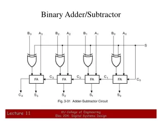
4-bit Binary Adder/Subtractor If S=0, performs A+B; if S=1, performs A-B XOR gates act as programmable inverters
n-bit Addition and Subtraction • The result will be the algebraically correct value in the 2's complement representation as long as the answer is in the range –2n-1 through 2n-1–1 • When answers do not fall within the range: arithmetic overflow • Exception occurs • The Add/Sub control wire is connected to C0 • To do addition, Add/Sub control wire set to 0 for addition • To do subtraction, Add/Sub control wire is set to 1, and the B vector is 1's complemented
n-bit Binary Addition-Subtraction Logic B B B n - 1 1 0 Add/Sub control A A A n - 1 1 0 n -bit adder c n c 0 s s s n - 1 1 0
Sign Extension in Binary Addition-Subtraction • Often we need to represent a given number in 2's complement by using a large number of bits • for positive numbers: add 0s to the left • for negative numbers : the sign bit '1' is replicated to the left as many times as needed (sign extension)
Overflow in Integer Arithmetic • When adding unsigned numbers, the carry-out cn serves as the overflow indicator • When adding signed numbers, we need another indicator • The addition of numbers with different signs cannot cause overflow because the absolute value of the sum is always smaller than the absolute value of one of the two summands • What about adding numbers with the same sign • Example: adding +7 and +4 in 4-bit adder, the output vector S = 1011 = -5 and the carry-out signal from the MSB is 0 • Add -4 and -6 , S = +6, and the carry-out signal is 1 0111 (7) + 0100 (4) = 1011 (-5) 1100 (-4) + 1010 (-6) = 0110 (+6)
Overflow Detection • Examine the MSB bit • Bottom line: • P: positive; N: negative • P+N or N+P always fall into the range • E.g. -128+P cannot be smaller than -128 or bigger than 127 • N + N = N • P + P = P • Problem lies in • N+N = P • P+P = N Discarded
Overflow Detection n-bit Adder/Subtractor Cn Overflow Cn-1 Discarded