Download
1 / 3
30 likes | 106 Views
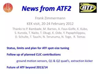
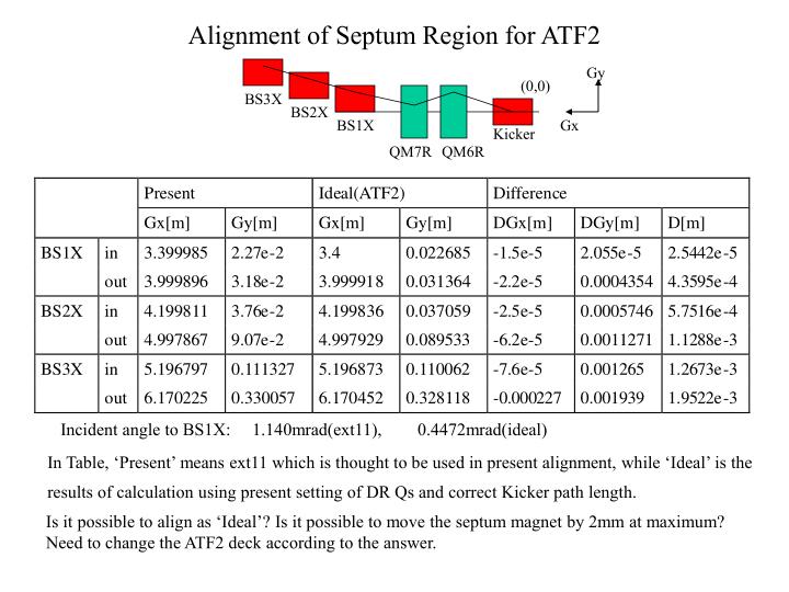
Alignment of Septum Region for ATF2. Gy. (0,0). BS3X. BS2X. BS1X. Gx. Kicker. QM7R. QM6R. Incident angle to BS1X: 1.140mrad(ext11), 0.4472mrad(ideal). In Table, ‘Present’ means ext11 which is thought to be used in present alignment, while ‘Ideal’ is the

E N D
Alignment of Septum Region for ATF2 Gy (0,0) BS3X BS2X BS1X Gx Kicker QM7R QM6R Incident angle to BS1X: 1.140mrad(ext11), 0.4472mrad(ideal) In Table, ‘Present’ means ext11 which is thought to be used in present alignment, while ‘Ideal’ is the results of calculation using present setting of DR Qs and correct Kicker path length. Is it possible to align as ‘Ideal’? Is it possible to move the septum magnet by 2mm at maximum? Need to change the ATF2 deck according to the answer.
Correction by Septum Fine Tuning In the Case of Present Alignment Fit DX=DPX=0 at Exit of BS3X Variables: K0 of Septum Magnets( Originally 0 ) BEND BS1X =(L =.3 ANGLE =-.0140178327098 K0 =9.839498985778E-5 ) BS2X =(L =.4 ANGLE =-.0371716830661 K0 =-1.78262582903E-4 ) BS3X =(L =.5 ANGLE =-.1175110129077 K0 =8.107427306212E-5 ) Need current change K0/ANGLE=7.03e-3(BS1X) 4.78e-3(BS2X) 6.88e-4(BS3X) Twiss parameter change at Exit of BS3X AX=1.65 AX=1.65 BX=8.29[m] BX=8.30[m] AY=-1.46 AY=-1.46 BY=4.47[m] BY=4.47[m] Calculation uses the initial values in the EXT deck, which need to be confirmed/measured. Anyway the changes in the optical functions are small enough to be absorbed downstream. This could be a realistic solution since re-alignment of septum magnets needs much work. ??
Constraint imposed; BS2X is coupled to BS1X with Angle(BS2X)/Angle(BS1X).( PS”BS1X” is common for BS1Xand BS2X ) BEND BS1X =(L =.3 ANGLE =-.0140178327098 K0 =-1.63514748725E-4 ) BS2X =(L =.4 ANGLE =-.0371716830661 K0 =-4.33599012206E-4 ) BS3X =(L =.5 ANGLE =-.1175110129077 K0 =2.549096590139E-4 ) Need current change K0/ANGLE=0.0117(BS1X) 2.16e-3(BS3X) Twiss parameter change at Exit of BS3X is the same as before. Correction by Septum Fine Tuning( cont. ) Orbit in Septum region