Download
1 / 26
270 likes | 278 Views
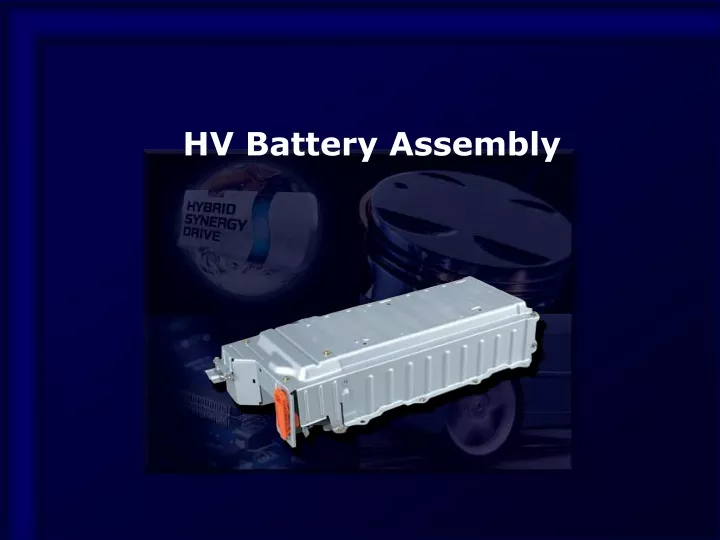
HV Battery Assembly. HV Battery Assembly. Power Supply The HV battery supplies power to MG1 / MG2 The auxiliary battery supplies power to HV ECU and Engine ECU (all ECU) When both are functioning properly, the vehicle will start. HV Battery (DC 201.6V). Auxiliary Battery (DC 12V).

E N D
HV Battery Assembly • Power Supply • The HV battery supplies power to MG1 / MG2 • The auxiliary battery supplies power to HV ECU and Engine ECU (all ECU) • When both are functioning properly, the vehicle will start HV Battery (DC 201.6V) Auxiliary Battery (DC 12V)
HV Battery Assembly • Components Module Current Sensor Battery ECU SMR3 SMR2 SMR1 Service Plug Connector Resister
HV Battery Assembly • Battery Module • Nickel metal hydride (Ni-MH) battery(1.2V x 6 cells) x 28 modules = 168 cells = DC 201.6 V 28 Module Module (1.2V x 6 cells)
SOC Control HV Battery Condition Detection Cooling Fan Control Electrical Leakage Detection for High-voltage System Diagnosis Function for HV Battery HV Battery Assembly • Battery ECU • Maintains control of HV battery SOC (State of charge) • Ensures battery capability Battery ECU CAN Battery Cooling Fan Relay • HV ECU • Engine ECU • A/C ECU Battery Cooling Fan Controller Voltage x 14 Temp. x 4 + Temp. Sensors (Thermistor) Service Plug Battery Cooling Fan Motor - CurrentSensor HV Battery
HV Battery Assembly • Battery ECU • Controls SOC to match THS characteristics • The SOC is maintained at approx, 60%. A margin is given for further recharging via regenerative braking • Sends requests to HV ECU to obtain desired SOC
Charge Request Power Request MG1 Control Voltage (SOC) Charge Drive HV Battery Assembly • SOC Control • When the SOC is dropped, battery ECU sends the “Charge Request” signal to HV ECU Battery ECU HV ECU Engine ECU SOC Charging HV Battery Engine
HV Battery Assembly • SMR (System Main Relay) • Turns ON / OFF the high-voltage circuit SMR3 SMR1 SMR2
HV Battery Assembly • SMR • When the power is ON (READY ON) STEP 1:SMR 1 / SMR 3 ON STEP 2:SMR 2 ON STEP 3:SMR 1 OFF
HV Battery Assembly • SMR • When the power is ON (READY ON) STEP 1:SMR 1 / SMR 3 ON STEP 2:SMR 2 ON STEP 3:SMR 1 OFF
HV Battery Assembly • SMR • When the power is ON (READY ON) STEP 1:SMR 1 / SMR 3 ON STEP 2:SMR 2 ON STEP 3:SMR 1 OFF
HV Battery Assembly • SMR • When the power is ON (READY ON) STEP 1:SMR 1 / SMR 3 ON STEP 2:SMR 2 ON STEP 3:SMR 1 OFF
HV Battery Assembly • SMR • When the power is OFF STEP 1:SMR 2 OFF STEP 2:SMR 3 OFF
HV Battery Assembly • SMR • When the power is OFF STEP 1:SMR 2 OFF STEP 2:SMR 3 OFF
HV Battery Assembly • SMR • When the power is OFF STEP 1:SMR 2 OFF STEP 2:SMR 3 OFF
HV Battery Assembly • SMR • System diagram Inverter SMR2 Service Plug Resister Voltage Sensor HV Battery Current Sensor SMR1 Interlock Switch (Inverter Cover) SMR3 Battery ECU HV ECU Interlock Switch (Service Plug) Power Switch Power Source Control ECU Airbag Sensor Assembly Circuit Breaker Sensor
HV Battery Assembly • SMR • Shutdown control READY OFF At Collision Interlock Switch OFF (Service plug grip disconnection, Inverter cover open)
HV Battery Assembly • Service Plug • Shut off the high voltage circuit manually Service Plug
HV Battery Assembly • Service Plug • Power is shut off at HV battery midpoint to avoid high voltage electricity flowing into the circuit
HV Battery Assembly • Service Plug • It contains a interlock switch and fuse Service Plug Service Plug Grip Fuse Cover Interlock Switch
HV Battery Assembly • Service Plug Caution: Wear insulated gloves [Removal] [Installation]
HV Battery Assembly • Cooling System • Battery ECU executes a command to switch cooling fan ON when battery temp. rises Air Inlet Cooling Fan Cooling Fan Controller Battery Module : Temp. Sensor
HV Battery Assembly • Cooling System • Cooling fan motor is stepless controlled Cooling Fan Controller Temp. Sensors (HV Battery) (V) 13 Cooling Fan Motor Duty Signal Output Voltage Cooling Fan Controller M Battery ECU 4 30 95 (%) Input Duty Ratio (from Battery ECU) A/C ECU
HV Battery Assembly • Auxiliary Battery • Auxiliary battery supplies power to headlights, audio, and all ECUs Auxiliary Battery
HV Battery Assembly • Auxiliary Battery • Sealed-type battery is used Notice: Refrain from quick charging Because the battery fluid cannot be replenished Never use an ordinary battery
HV Battery Assembly • Auxiliary Battery • Jump Start Terminal • ”+” terminal of auxiliary battery for jump start is used Jump Start Terminal