Download
1 / 16
190 likes | 536 Views
Transformer Construction. Three-Phase Transformer. Transformer Action -- DC. Opposes battery voltage. Opposes flux buildup. Transformer Action -- AC. Opposes V T Opposes Φ M. “No-Load” Condition. “No load” condition continued. I o = I fe + I M

E N D
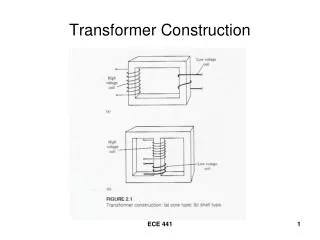
Transformer Construction ECE 441
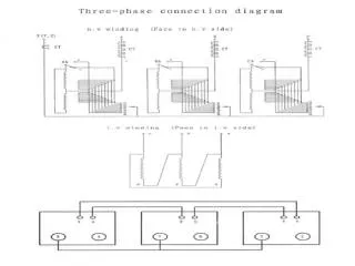
Three-Phase Transformer ECE 441
Transformer Action -- DC ECE 441
Opposes battery voltage Opposes flux buildup ECE 441
Transformer Action -- AC ECE 441
Opposes VT Opposes ΦM ECE 441
“No-Load” Condition ECE 441
“No load” condition continued Io = Ife + IM Io = exciting current Io provides the “magnetizing flux” and the “core loss” Ife = core-loss current Ife = VT / Rfe IM = magnetizing current IM = VT / jXM ECE 441
No-Load Excitation mmf Magnetizing mmf No-Load Core Loss mmf ECE 441
Close the load switch Secondary current will set up an mmf in OPPOSITION to the primary mmf. The core flux will DECREASE to ECE 441
The decrease in flux causes a decrease in the counter-emf EP, and the primary current will increase by an amount known as IP,load, the load component of the primary current. Additional mmf due to this current adds to the magnetizing flux. ECE 441
Primary current increases until NPIP,load = NSIS. The flux ΦM and primary emf EP return to the same values as before the switch was closed. ECE 441
Final steady – state primary current under loaded conditions is ECE 441
ΦP = net flux in window of primary ΦS = net flux in window of secondary Φlp = leakage flux of primary Φls = leakage flux of secondary ΦM = mutual flux ΦP = ΦM + Φlp ΦS = ΦM – Φls ECE 441