Download
1 / 13
140 likes | 378 Views
Unit Transformer. Unit transformer are step up transformer which is connected to generating house & step up voltage from 15kV voltage to 132 voltage level as requirement or line design parameter.

E N D
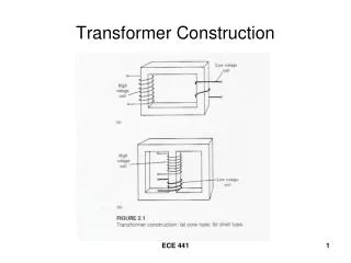
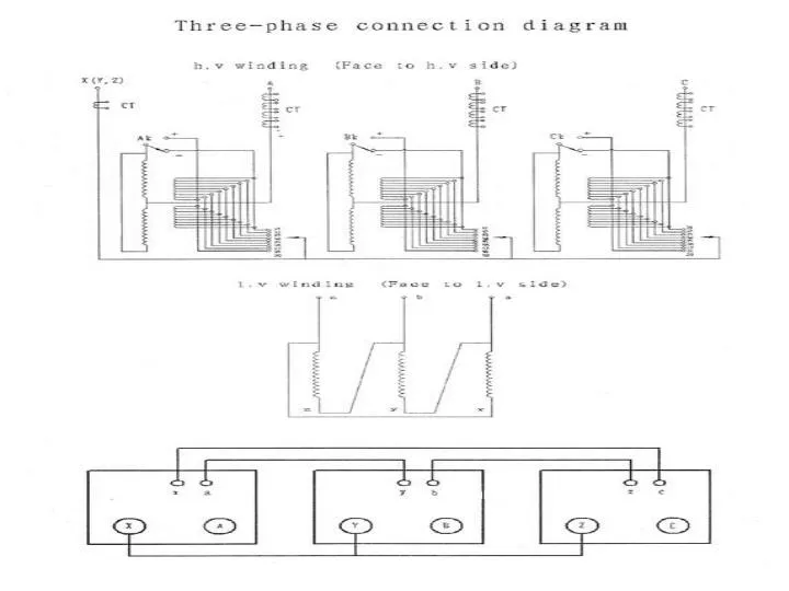
Unit Transformer • Unit transformer are step up transformer which is connected to generating house & step up voltage from 15kV voltage to 132 voltage level as requirement or line design parameter. • It is just like transformer but connected to unit of the generating house that's why we called it unit transformers. • Transformers used in three-phase systems may consist of a bank of three single-phase transformers or a single three-phase transformer which is wound on a common magnetic core. • In Tongi power plant they use three single phase transformer which make a bank and produce three phase supply. Fig: Unit Transformer used in Tongi plant
Cont. Main transformer specifications: Application standard IEC 60076 Rated parameters Type DFZ-55000/132W2 TH (single-phase composite type) transformer) Cooling type ONAN/ONAF (75%/100%) Frequency 50Hz Impedance voltage 16% Rated power 3×550000kVA Rated voltage 132/√3×(1±8×1.25%)/15kV Wiring Ynd1 Insulation level LI650AC275-LI650AC275/LI105AC45 Rated current 721.69/6350.85A
Current Transformer Current transformers are used for reducing/stepping down a.c. current from higher value to lower value for measurement /protection/control.Typical secondary current of CTs are 5A or 1A r.m.s There are two classes of current transformer: Measuring current transformer Protective current transformer Fig: Current Transformer used in Tongi plant
Cont.. • Here is difference between the protection CT and metering CT in operating conditions… • The CT using for protection will have to carry the fault currents which are 10 times the normal full load current. • The CT used for metering will have to carry only full load current
Voltage transformer Voltage transformers are use for measurement and protection. It stepping down the voltage for the purpose of protection, measurement and control. The primary of voltage transformer is connected directly to power circuit between phase and ground depending upon rated voltage and application. Typical secondary voltage of VTs are 110V or 100V. Fig: Voltage transformer used in Tongi plant
When a fault occurs in the protected circuit, the relay (2) connected to the CT an PT actuates and closes its contacts (6). Current flows from the battery (5) in the trip circuit (4). As the trip coil of the circuit breaker(3) is energized, the circuit breaker operating mechanism is actuated and it operates for the opening operation. The trip circuit