ADV728x-M MIPI Interface Tips
140 likes | 831 Views
ADV728x-M MIPI Interface Tips. The following document gives tips on how to help customers interfacing the ADV7280-M, ADV7281-M, ADV7281-MA or ADV7282-M with MIPI CSI-2 receiver systems. D-PHY Output Mode.

ADV728x-M MIPI Interface Tips
E N D
Presentation Transcript
ADV728x-M MIPI Interface Tips The following document gives tips on how to help customers interfacing the ADV7280-M, ADV7281-M, ADV7281-MA or ADV7282-M with MIPI CSI-2 receiver systems.
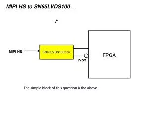
D-PHY Output Mode • The D-Phy of the MIPI CSI-2 receiver needs to be able to detect the mode of operation of the ADV728x-M. • E.g. High Speed mode (HS), Low Power mode (LP), and Ultra Low power mode (LP-00). • The ADV728x dynamically switches into/out of HS and LP states during normal opeation. • Different termination is needed in the receiver D-Phy for each mode of operation. • These modes should be manually programmed on the ADV728x-M and the MIPI CSI-2 receiver should be tested to see if it can detect each of these modes. • The ADV728x hardware manual describes how to program the ADV728x-M to output each of these modes of operation. • Some MIPI CSI-2 receivers wait for a LP to HS transition on the MIPI CSI-2 clock lane. • This only happens once on the ADV728x-M models, directly after the ADV728x-M is initially programmed. • This transition can be forced by toggling the CSITX_PWRDN bit (CSI MAP, Address 0x00[7])
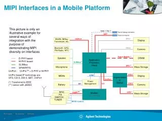
Example of MIPI Signal 1.2 V HS Termination Off 400 mV 200 mV 0 V SoT Sequence 011101 HS Termination On • Connect the MIPI Tx to the MIPI receiver and measure the output with an oscilloscope. • Data lanes In Low Power mode • Logic High is 1.2V • Logic Low is 0V • Data lanes In High Speed mode • Logic High is 400mV • Logic Low is 200mV • Clock lanes enter High Speed mode (200 mVpp, 108MHz) and remain in that mode until power down. • If any other voltage level is seen on the MIPI lines then D-PHY termination is not being performed correctly at the reciever.
Output Video Format • The ADV728x-M always output in a YCbCr 4:2:2 color space. • By default the ADV728x-M output video in an interlaced format. • The MIPI CSI-2 receiver needs to perform a deinterlacer function on the output video. • Alternatively some ADV728x-M models have a built in deinterlacer (I2P core). • The ADV728x-M can output in a ITU.BT656-3 or ITU.BT656-4 format. • E.g. For NTSC inputs in ITU.BT656-3 mode: • For odd frames 254 lines of active video are output. • For even frames 253 lines of active video are output. • Note the one line extra in odd frames !
MIPI CSI-2 Packets • Short Packets • By default the ADV728x-M always outputs line start/end short packets and frame start/end packets. • Only frame start/end packets are mandatory under the MIPI Spec. • Long Packets. • The Data ID bits in the packet header of long packets will always state that the data is in a YCbCr 4:2:2 format. • The virtual channel identifier is 0b’00 by default. This can also be set to 0b’01, 0b’10, 0b’11 by setting the VC_REF bits (CSI Map, 0x0D[7:6]) • Free-run mode • The ADV728x-M can be programmed into free-run mode. In this mode the ADV728x-M outputs a fixed test pattern. This can help customers debug issues with the MIPI receiver system.
Layout Tips • The MIPI traces should be kept as short as possible • As a rule of thumb under 30cm. • Characteristic impedance of 50 Ohm. • The differential lines should be ‘loosely coupled’. This is because the positive and negative lines are differential in HS mode and single-ended in Low Power mode. • MIPI traces should be fed from one ADV728x-M to one MIPI CSI-2 receiver. • It is not possible to daisy-chain a number of ADV728x-M’s into one MIPI CSI-2 receiver. • All filtering /termination is performed in the D-PHY of the ADV728x-M and in the D-PHY of the receiver. • No not place any additional components (i.e. capacitors, ESD diodes, resistors) on the MIPI CSI-2 traces.
MISC • The ADV728x-M require a nominal DVDDIO of 3.3V • i.e. a DVDDIO voltage of 1.8 V will cause the ADV728x-M not to work correctly • Read registers 0x10 to 0x13. • This will tell if the ADV728x-M has locked correctly to the incoming video source. • Crystal Oscillator • The crystal oscillator does not oscillate until the ADV728x-M has been programmed out of power-down mode. • The crystal for the ADV728x devices need to have a fundamental frequency of 28.636363MHz and have a tolerance of +/- 50ppm over the temperature range of operation.