Download
1 / 26
260 likes | 401 Views
ERL Sessions. Bettina Kuske and Susan Smith + Joint Session Convenors + Contributing Speakers. ERL Sessions Susan Smith & Bettina Kuske. Status and news (4 talks Monday) Miscellaneous (2 talks & Tom Powers (2)) inverse Compton scattering of CSR (Compact Linac)

E N D
ERL Sessions Bettina Kuske and Susan Smith + Joint Session Convenors + Contributing Speakers
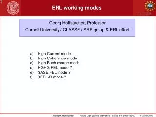
ERL SessionsSusan Smith & Bettina Kuske • Status and news (4 talks Monday) • Miscellaneous (2 talks & Tom Powers (2)) • inverse Compton scattering of CSR (Compact Linac) • ERL Cryomodule Development in Japan • Joint with Storage Rings ERLs Vs USR • Joint with Sources I Injectors (4 Talks) • Joint with FELs XFELO (2 Talks) • Limits of Recirculation (2 Talks) • Modelling (3 Talks) • Joint with Sources II Injectors Pulse shaping (2 Talks) • Joint with Sources & Diagnostics Unwanted beam ( 3 Talks) 25 Talks
Status and News ALICE Susan Smith ERLs in Japan Shogo Sakanaka Compact ERL 3GeV ERL Light Source Dave Douglas BERLinPro JLAB ERL/FELs Andreas Jankowiak
Now lasing CW again in the IR • THz beamline • ~10s of W @ 0.2 – 1.5 THz • IR FEL • High power FEL, optics, beam dynamics studies • 14+ kW at 1.6 microns; several kW @ multiple wavelengths • UV FEL • Recently commissioned (summer 2010) • High power (100+W) CW 700, 400 nm • Coherent harmonics into VUV (10 eV) E E E E f f f f E E f f Machine overhaul, upgrade during next long shutdown DC Gun IR Wiggler JLAB ERL/FELs SRF Linac Dave Douglas Bunching Chicane JLab IR Demo Dump Sextupoles (B’dL)12730 G Sextupoles (B’dL) 10730 G Dump Sextupoles (B’dL) 8730 G core of beam off center, even though BLMs showed edges were centered (high energy tail
ALICE Susan Smith Characterise in ALICE 2013
commission cERL, hopefully, in March, 2013 Plan of Laser Compton Scattering Experiment by JAEA
First beam 21st April 2011 18.3 MV/m 0. 1.8MeV 6pC bunch charge 8kHz (~50nA) BERLinPro Andreas Jankowiak 3 x 2-cell Cornell-type 270 kW transmitters beam through booster envisaged 2015 • BESSYVSR
BESSY II: 200mC / a @ 1.7GeV typicalBERLinPro: some 100mC / 1s @ 50 MeV possible (30kW linac RF-power) BERLinPro Radiation regulatory body proof ERL SHIELDING @ 100 mA Compact ERL Earthquake proof
MihoShimada: Inverse Compton scattering of CSR(CSR-ICS) • Magic mirror : White light with pulse duration of 100 fs. Optical cavity : Narrow bandwidth.Power amplification by pulse stacking: almost 1000 times. CSR is reflected at a mirror and collides with the following electron bunch. M. Shimada, R. Hajima, PRSTAB 13, 100701, 2010
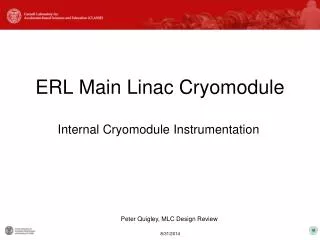
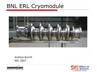
Hiroshi Sakai: ERL Cryomodule Developmentin Japan LINAC Frequency : 1.3 GHz Input power : 20 kW CW /coupler Gradient: 20MV/m Q0: >1*10^10 Beam current: 100mA(initial 10mA) INJECTOR Frequency : 1.3 GHz Input power : 170 kW CW /coupler Gradient: 15MV/m Q0: >1*10^10 Beam current: 100mA(initial 10mA) Two cavities reached up to 25MV/m and satisfied cERL requirements of 1*10^10 of Q0 at 15MV/m. All 3 cavities satisfied the cERLrequirements with improved HOM couplers 2 cavities (#3, #5) > 25MV/m #4 cavity up to 20MV/m t Simulation with Fishpactbased on Fowler-Nordheimequation -mode 13.9MV/m • Conditioning Results Coupler: • 1s, 0.1Hz, 100kW for 2h • cw 30kW for 1.5h • cw 50kW for 0.5h • (ok for 10mA) • cw 100kW for 1 min Done by E.Cenni We found the emission source would make the radiation peak at opposite side and also make the radiation peak at other iris point.. Heating inner conductor of warm part Test with improved cooling soon Both cryo modules will be constructed during 2012
Tom Powers Cost Calculator Inputs
Joint sessionwithstorage rings: Christof Steier / Ivan Bazarov: USR versus ERL Comparisonandpotential synergies Benefits of USR has a strong orientation towards typical ERL features: short pulses, high coherence, round beams, flexible operation modes, reduced no. of turns Special operating modes: – Single/few-turn, sub-ps bunch mode – Crab cavity short pulse scheme (shorter bunches plus smaller emittance might allow much shorter pulses compared to SPX) – 100-1000 turn mode, enabling very low emittance with reduced dynamic aperture, requiring injection of fresh electrons from a superconducting linac operating without energy recovery (e.g. ~1 mA @ few GeV) – localized bunch compression systems with components located in long straight sections – bunch tailoring with low alpha, non linear momentum compaction, multiple RF frequencies – lasing in an FEL located in a switched bypass, where the post-lasing electron bunches are returned to the storage ring for damping – partial lasing at soft X-ray wavelengths using the stored beam, requiring high peak current created by localized bunch manipulation USR lattices and optimization procedures become highly complex, but using existing technologies ERLs just start off and future potentials will develop after ‘generation 1’ goes online
Joint session:Sources I- Injectors for ERLs Andrew BurrillRequirementsandfirstideas Injectordevelopment BERLinPro T. Kamps SRF gun – beam studieswithPbcathode KEK T. Miyajima DC gun reached > 500kV JAEA N. NishimoriDC gunreached > 500kV Three areas future collaboration • Emittance and longitudinal bunch properties vs charge • Operating cathode lifetime and integrated charge per cathode intervention • Field emission • Removal methods (HV, wiping, gas processing & others) • Characterisation (location, causes etc.) 50 mA record and 35 mA sustainable (Cornell)
Joint session with FEL: XFELO Shogo Sakanaka: Plans of XFELO in Future ERL Facilities Ryan R. Lindberg: Overview of XFELO parameters Cornell – XFEL-O plans: 7.8 GeV 25m insertiondevice - or 5GeV withcompressedbunches lrf/2 path-length changer 6 (7) GeV XFEL-O in 2nd stage 3GeV ERL in the first stage Lindberg: Possibilitiesbeyondthecanonical K.-J.-Kim parameters User‘sinputneeded
Mike Borland Jim Clarke Limits of Recirculation • Effects of Several VLongUndulators • in the APS ERL Design The impact of undulators in 4GLS • 7 GeV, 9 x 48m undulators K=5, 55mm • Energy shift 1.4 MeV noticeable • Use of booster cavities seems advisable • 600MeV, 10 m 1 T hel. Undulator • Energy shift 4.6 keV negligible • Negligible emittance growth • Negligible energy spread • CSR in arcs ~1MeV ! • Path length change 300fs for long undulator • Use path length chicane seems advisable (feedforward) • Photon pulse lengthening due to long undulator ~ 150 fs, 30fs short • Impact on beam dynamics in general of the varying focussing and non-linear terms was not studied • Energy spread increase is fairly modest c.f. CSR increase • Final energy spread of ~1.3 MeV with all gaps closed • No emittance growth seen • Conclusion should be checked with realistic optics errors (i.e., dispersion leaking into straight sections M. Borland, G. Decker, X. Dong, L. Emery, A. Nassiri, Proc. PAC09, 44- (2009). (http://www.4gls.ac.uk/)
ALICE Beam Simulations Deepa Angal-Kalinin Injector dynamics complicated by reduced gun energy (230 KeV), long multi-cell booster cavity and long transfer line. Elliptical beam – effect of stray fields? BC1 Phase -20deg -10deg -5deg Using ASTRA and GPT to go around the machine to understand longitudinal dynamics. Non trivial to use dipoles. GPT (Space charge off) and MAD matching quite good, small differences in vertical focussing. Bunch-length vs. Linac Phase 4.65mm 10mm ALICE in GPT Plan to validate 6D machine model to understand different machine set ups with additional diagnostics . D. Angal-Kalinin
Miho Shimada: Lattice and optics design of both compact ERL and 3-GeV ERL projects • enx increases step by step at every each arc. • In the first inner loop : 1 mm-mrad • In the outer loop : 5 mm-mrad • The low emittance beam is difficult for 2 loop ERL compared with 1 loop ERL • Injection/ dump energy: 10 MeV, full energy: 3 GeV • Circumference ~2000 m, linac length : 470 m • 22 x 6 m short straight , 6 x 30 m long straight • 28 cryo modules, 8 x 9-cell cavities per cryo module • field gradient: 13.4 MV/m, focusing triplets • Deceleration symmetric to the acceleration • Achromatic and isochronous TBA optics in arcs r~20m 1 mm-mrad 9 mm-mrad 5 mm-mrad Acceleration Deceleration
Yichao Jing: Bunch compressor design for FEL @ eRHIC Studies for eRHIC FEL Choose low energy (~ 10 GeV) for FEL to avoid severe blow up in both emittance and energy spread caused by synchrotron radiation. Normalized emittance assumed to be 0.2 μm in simulation. Phase space plots show clear evidence of emittance spoil due to the longitudinal – transverse coupling in chicanes. C-type chicane 2 Opposite bending direction Smaller bending strength C-type chicane 1 Phase shifter Reduction of emittance growth Promising FEL performance
Core emittance Joint sessionwithSources II: Pulse shaping Mikhail Krasilnikov: Cathode Laser Pulse Shaping for High Brightness Electron Sources (PITZ Experience) Significant progress in performance and understanding FlatTop Reduced halo Gauss halo Ellipssid No halo Electron beam transverse distribution at z=5.74m
Joint sessionwithSources II: Pulse shaping Torsten Quast: Available and Future Pulse Shaping Technologies FWHM ~ 24 ps FWHM ~ 19 ps FWHM ~ 24 ps FWHM ~7 ps FWHM ~ 2 ps Discussion: “Is it worth the effort?” Simple schemes are more reliable and stable Max. gain is 40% - but factors of 2 easily lost else where Benefit depends on application – emittance not unique figure of merit Blow out regime attractive for halo reduction insensitive towards laser parameters Takenfrom: Will, Klemz, Optics Express 16 (2008) , 4922-14935 High precision pulse shaper (MBI)
Joint session with Sources III: Unwanted beam ELBE J. Teichert Unwanted beam observations at ELBE PITzM. KrasilnikovProblems observed at PITZ: measurements vs. simulations JLAB P. Evtushenko Diagnostics Related to the Unwanted Beam Five sorts of the unwanted beams • Dynamics: Fraction of the phase space distribution that is far away from the core (due to the beam dynamics), wake fields, resonant HOM excitation • Laser 1: Low charge due to not well attenuated Cathode Laser (ERLs) – but real bunches that have proper timing for acceleration, • Laser 2: Cathode Laser but not properly timed (scattered and reflected light) • Field emission: Dark current or discharges Gun (can be DC or RF), Accelerator itself (can be accelerated in both directions) • RF: microphonics, phase and amplitude instabilities
“The Grand Scheme” P. Evtushenko I. Transverse beam profile measurements with LargeDynamic Range Wire scanner LDR imaging CW laser wire Coronagraph II. Transverse phase space measurementswith LDR III. Longitudinal phase space with LDR(in injector at 9 MeV) Drive Laser LDR measurements to start modeling with LDR and real Initial conditions • transverse • longitudinal • cathode Q.E. 2D Tomography – where linear optics work (135 MeV) Time resolving laser wire (Thomson scattering, CW) Scanning slit - space charge dominated beam (9 MeV) Transverse kicker cavity + spectrometer + LDR imaging IV. High order optics to manipulatehalo V. Beam dynamics modeling with LDR
Problems observed at PITZ: measurements vs. simulations Mikhail Krasilnikov 1nC 0.1nC
Unwanted Beam Observations at ELBE J. Teichert laser pulsed RF 100 ms courtesyof F. Obier/DESY 20% Cathode (80% scratch on cavity) 10 ms Dark current kicker bunch 100 pC assuming an unwanted beam of < 1 µA in CW accelerators with SRF guns there will be a need for photo cathodes with low dark current proper handling to prevent dust particles and damage plug materials and roughness photo layer properties - roughness, homogeneity, thickness - high work function - crystal size and structure - multi-layer design - post-preparation treatment (ions, heating) - pre-conditioning darkcurrentat 1.3 GHz 10 ms Pulsed operation