Download
1 / 12
120 likes | 151 Views
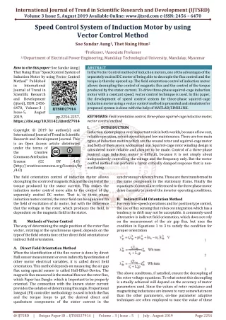
A Study on Motor Speed Control. System Equations. KVL and Newton’s 2’nd law gives :. Let : Output : y = Input : u = v a Disturbance w = T l. Laplace transforming, we obtain :. Transfer Functions. Where:. System Parameters.

E N D
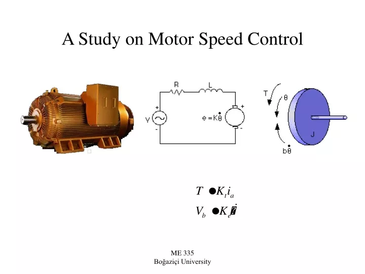
A Study on Motor Speed Control ME 335 Boğaziçi University
System Equations KVL and Newton’s 2’nd law gives : Let : Output : y = Input : u = va Disturbance w = Tl Laplace transforming, we obtain : ME 335 Boğaziçi University
Transfer Functions Where: ME 335 Boğaziçi University
System Parameters For this example, the following values for the physical parameters will be assumed. • moment of inertia of the rotor (J) = 0.0001 kg.m2/s2* damping ratio of the mechanical system (b) = 0.0 Nms* electromotive force constant (K=Ke=Kt) = 0.01 Nm/Amp* electric resistance (R) = 0.1 ohm * electric inductance (L) = 0.0005 H* input (V): Source Voltage* output (): angular velocity of shaft * disturbance (Tl) : Load torque • * The rotor and shaft are assumed to be rigid Reference : http://www.engin.umich.edu/group/ctm/index.html ME 335 Boğaziçi University
Numerical Values J=0.0001; b=0.0; Ke=0.01; Kt=0.01; R=0.1; L=0.0005; A=Kt/(b*R+Kt*Ke);A=100 B=1/(b*R+Kt*Ke);B=10000 den=[J*L/(b*R+Kt*Ke) (J*R+b*L)/(b*R+Kt*Ke) 1]; r = roots(den); tau1= -1/r(1); tau2=-1/r(2);tau1 = 0.0947 s.: mech. time constant tau2 = 0.0053 s.: electrical time constant. ME 335 Boğaziçi University
Open Loop Step Response step(A,den,0:.05:1.5) title('Step Response for the Open Loop System') ME 335 Boğaziçi University
Steady State Model yss = 100 u + 10000 w where y is in rad/s, u is in Volts and w is in N/m. For example, u = va = 1.5 Volts gives ss = 150 rad/s = 1432 rpm. If w = Tl = -0.002 N m., then ss = 150 - 20 = 130 rad/s = 1241 rpm. Result : Without control, the speed decreases (or increases) proportional to w. Controller must increase (or decrease) u, to compensate for the effect of disturbance. ME 335 Boğaziçi University
100 4.2 Disturbance : Gain Load Torque Tl Ref. 1.5 signal (Volts) Steady state Voltage input x' = Ax+Bu PID y = Cx+Du Saturation Motor PID Controller DC MOTOR speed Voltage input 0.028 TACHOMETER Feedback Control Simulink block diagram Input saturation : Input voltage va can be between 0 and 2.5 volts Measurement : Tachometer gain : 0.028 Volts/rad/s Reference signal : 150 rad/s * 0.028 Volts/rad/s = 4.2 Volts; is compared with tachometer output. ME 335 Boğaziçi University
Proportional Control yref is increased from 150 to 160 rad/s. There is ss. error, ss. error decreases as KP is increased ME 335 Boğaziçi University
Disturbance Rejection A step torque disturbance of Tl = -0.002 Nm. is applied Compared to no control (130 rad/s), there is improvement, still there is ss. error. ME 335 Boğaziçi University
PID Controller Control signal is a linear combination of error, integral of error and time rate of change of error. ME 335 Boğaziçi University
PID Control of DC Motor No steady state error, good response. ME 335 Boğaziçi University