Download
1 / 17
180 likes | 336 Views
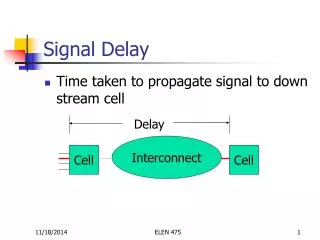
Phase Delay in MAC-based Analog Functional Testing in Mixed-Signal Systems. Jie Qin, Charles Stroud, and Foster Dai Dept. of Electrical and Computer Engineering 200 Broun Hall, Auburn University, AL 36849-5201 emails: qinjie1/strouce/daifa01@auburn.edu. Outline. Motivation and Background

E N D
Phase Delay in MAC-based Analog Functional Testing in Mixed-Signal Systems Jie Qin, Charles Stroud, and Foster Dai Dept. of Electrical and Computer Engineering 200 Broun Hall, Auburn University, AL 36849-5201 emails: qinjie1/strouce/daifa01@auburn.edu VLSI Design & Test Seminar Series
Outline • Motivation and Background • Built-In Self-Test Architecture • Phase Delay in the MAC-based ORA • Experimental Results • Conclusions VLSI Design & Test Seminar Series
Motivation and Background • Why mixed-signal BIST? • The increasing cost of functionality test based on the traditional methodology of external test equipment for modern mixed-signal ICs. • The increasing difficulty to perform test on these ICs. • With a rapidly increasing level of integration, the number of input/output (IO) pins does not increase accordingly. • The operational frequency of latest analog ICs at GHz requires tester electronics very close to the DUT. VLSI Design & Test Seminar Series
Motivation and Background (cont.) • What should a mixed-signal BIST be? • It can extract the frequency spectrum information of the signal coming from the DUT. • Linearity Measurement • Frequency Response • Signal-to-Noise Ratio Measurement • It should be implemented using simple circuitry with small area penalty and should not cause performance penalty to analog circuitry. • The conventional way to obtain the frequency spectrum is FFT. However, the area penalty and power consumption introduced by a FFT processor is not what a BIST expects. VLSI Design & Test Seminar Series
Motivation and Background (cont.) • The BIST approach based on the DDS-based TPG and MAC-based ORA was proposed. • DDS-based TPG can generate various waveforms which is required for the linearity, frequency response, and SNR measurement. • MAC-based ORA could be realized in a much simpler, cheaper and more flexible circuit, compared with the FFT-based ORA. VLSI Design & Test Seminar Series
Built-In Self-Test Architecture Amp DAC • Most of the BIST circuitry resides in the digital portion of the mixed-signal system. In such a way, the performance penalty are minimized. • The number and location of the MUX inserted to the system determines the accuracy of the analog functional measurements. Test Controller DUT MUX3 f1’, 1 Sin(2f1’nTclk+1) NCO1 ADC MUX1 f2’, 2 Sin(2f2’nTclk+2) NCO2 MUX4 Output Response Analyzer (ORA) f(nTclk) Test Pattern Generator (TPG) f1(nTclk) MUL1 DC1 Accm1 MUX2 f2(nTclk) f3’, 3 Sin(2f3’nTclk+3) DC2 MUL2 NCO3 Accm2 VLSI Design & Test Seminar Series
MAC-based ORA • While performing the analog functional testing, the DC1 and DC2 accumulator values can be described as • Then the the signal f(nTclk)’s Fourier Transform F() can be expressed through DC1 and DC2 • The magnitude response A() and the phase delay ΔΦ() are the two parameters widelyused much more widely in functional measurements of analog circuits. VLSI Design & Test Seminar Series
Phase Delay in MAC-based ORA • How can the phase delay be evaluated? • For an on-chip test, we don’t have to set up a full-length arctan look-up table (LUT) to calculate ΔΦ(). • First the absolute phase offset ΔΦo() need to be calculated according to the following formula: VLSI Design & Test Seminar Series
Phase Delay in MAC-based ORA (cont.) • Then the phase delay can be determined through the absolute phase offset ΔΦo() according to the following table: • The arctan look-up table (LUT) can be decreased by half because the value range of ΔΦo() varies from 0 to 45.when DC2/DC1 is very small, the arctan(DC2/DC1) can be represented by the ratio of the DC2/DC1. So the length of the arctan look-up table (LUT) can be compressed further. VLSI Design & Test Seminar Series
Phase Delay in MAC-based ORA (cont.) • Once the phase delay is identified, the magnitude response A() can be calculated through the following approaches. • Approach #1 • Approach #2 • Approach #3 VLSI Design & Test Seminar Series
Phase Delay in MAC-based ORA (cont.) • Pros and cons of the three approaches VLSI Design & Test Seminar Series
Experimental Results I • The phase delay introduced by the digital portion of the BIST circuitry. phase error due to the delay in TPG phase error with delay removed VLSI Design & Test Seminar Series
Experimental Results II • The phase delay introduced by the ADC/DAC pair VLSI Design & Test Seminar Series
Experimental Result III • The resources used by the MAC-based ORA. Number of slices vs. MAC configuration Number of LUTs vs. MAC configuration VLSI Design & Test Seminar Series
Experimental Result IV • The resources used by a FFT-processor VLSI Design & Test Seminar Series
Comparison of the MAC-based ORA and FFT-based ORA • MAC-based ORA is much simpler and cheaper. • MAC-based ORA is more flexible. • the frequency resolution can be easily tuned with the step size of the sweeping frequency; • it can measure the interested spectrum information at several frequency points or in a narrow bandwidth easily. VLSI Design & Test Seminar Series
Conclusion • phase delay is very important to the implementation and accuracy of the MAC-based ORA. • In comparison with the FFT-based approach, the MAC-based ORA can be realized using much more flexible and simpler BIST circuitry with less area penalty, which is what an ideal BIST scheme is supposed to be. VLSI Design & Test Seminar Series