Download
1 / 49
520 likes | 655 Views
Overview of laser, timing, and synchronization issues John Corlett , Larry Doolittle, Bill Fawley, Steven Lidia, Bob Schoenlein, John Staples, Russell Wilcox, Sasha Zholents LBNL. Scientific goal - application of ultrafast x-ray sources to study dynamics with high-resolution. x-ray probe.

E N D
Overview of laser, timing, and synchronization issues John Corlett, Larry Doolittle, Bill Fawley, Steven Lidia, Bob Schoenlein, John Staples, Russell Wilcox, Sasha Zholents LBNL
Scientific goal - application of ultrafast x-ray sources to study dynamics with high-resolution x-ray probe time delay detector visible pump diffraction angle time delay f(r) r visible pump absorption x-ray probe delay time energy K edge • Diffraction and spectroscopy • Nuclear positions and electronic, chemical or structural probes Time-resolved x-ray diffraction Time-resolved EXAFS NEXAFS Plus photoelectron spectroscopy, photoemission microscopy, etc • Access new science in the time-domain x-ray regime
Pump-probe experiment concept Laser excitation pulse sample ∆t ion or e- detector X-ray probe pulse g-detector • Ultrafast laser pulse “pumps” a process in the sample • Ultrafast x-ray pulse “probes” the sample after time ∆t • Ultrafast lasers an integral part of the process • X-rays produced by radiation in an electron accelerator
Pump-probe experiment concept Laser excitation pulse sample ∆t ion or e- detector X-ray probe pulse g-detector • Both laser and x-ray pulses should be stable in temporal and spatial distributions • Parameters and quality of x-ray pulse determined by the electron beam • Accelerator parameters • Synchronization between laser and x-ray pulses, ∆t, should ideally be known and controllable - to the level of the pulse duration itself ~ 10 fs
Many projects around the world are addressing the need for ultrafast x-rays, in different ways • LCLS: linac SASE (construction) • BNL DUV FEL: linac HGHG (operational) • DESYTTF-II: linac SASE (construction) • SPPS: linac spontaneous emission from short bunches (operational) • ALFF: linac SASE • BESSY FEL: linac HGHG • European X-ray FEL: linac SASE • Daresbury4GLS: ERL HGHG + spontaneous • LUX: recirculating linac HGHG + spontaneous • Cornell ERL: ERL spontaneous • MIT-Bates X-ray FEL: linac HGHG + SASE • Arc-en-Ciel: recirculating linac / ERL HGHG + SASE • FERMI@Elettra: linac HGHG • BNL PERL: ERL spontaneous
What are the difficulties in achieving x-ray beam quality? • X-rays are produced by electrons emitting synchrotron radiation in an accelerator • The electron beams are manipulated by rf and magnetic systems • The x-ray beam quality is limited by the electron beam quality in many ways • Electron bunch charge, energy, emittance, energy spread, bunch length, position, … • At the radiator! • Production of high-brightness bunches is tough enough • Emission process, space charge, rf focusing, …. • Then we must accelerate and otherwise manipulate the bunches before they reach the radiating insertion device • Many opportunities to degrade the electron bunch • Space charge, rf focussing, emittance compensation, CSR, geometric wakefields, rf field curvature, resistive wall wakefields, optics aberrations, optics errors, alignment, rf phase errors, rf amplitude errors, …
Synchronization • In addition to the electron bunch properties, the need for synchronization of the x-ray pulse to a reference signal - the pump - is required for many experiments • Time between pump signal and probe x-ray pulse • Predictable or measurable • Stable to ~ pump & probe pulse durations • This presents additional demands on the accelerator, instrumentation, and diagnostics systems • Various techniques may be employed to enhance synchronization • Slit spoiler for SASE • Seeding • HGHG • ESASE (Enhanced SASE) • e- bunch manipulation & x-ray compression • Measurement of relative x-ray - pump laser timing • Electro-optic sampling of electron bunch fields • Time-resolved detection of x-ray and laser pulses at the sample
The roles of lasers, timing,and synchronization in an ultrafast x-ray facility • Laser systems • Generate the high-brightness electron beam in an rf photocathode gun • Produce the pump signals at the beamline endstations • Timing system • Provides reference signals to trigger (pulsed) accelerator systems • Provides reference waveforms to synchronize rf systems • Provides reference waveforms to synchronize endstation lasers • Synchronization • To control and determine the timing of the x-ray pulse with respect to a pump pulse • Requires stable systems in the x-ray facility, connected by a “stable” timing system including stable timing distribution systems • The timing system only has to be “stable” enough for all of the components connected to it to follow it’s timing jitter (to the required level) • Phase noise ˛ timing jitter • The majority of the timing jitter must be within the bandwidth of the accelerator & laser systems such that they can follow • Local feedback around rf & laser systems • Lock to timing system master oscillator
Some space and time parameters for a conceptual ultrafast x-ray facility Bend magnets / compressor rf photocathode gun Linac Undulators End stations Length scale ~ 100’s m Time scale ~ µs Equivalent bandwidth ~ 100’s kHz • 10 fs ≈ 3 µm at c • Thermal expansion for ∆T = 0.1°C in Cu over 100 m • ≈ 170 µm or 570 fs • Similar magnitude effect from refractive index change in optical fiber
Some rf systems parameters for a conceptual ultrafast x-ray facility Bend magnets / compressor rf photocathode gun Linac Undulators End stations • 10 fs ≈ 5x10⁻³ °rf phase L-band • Cavity filling time (Q=104) ≈ 2 µs • Bandwidth ~ 100 kHz • Cavity filling time (Q=107) ≈ 2 ms • Bandwidth ~ 100 Hz • 10 fs ≈ 1x10⁻² °rf phase S-band • Cavity filling time (Q=104) ≈ 1 µs • Bandwidth ~ 300 kHz
Synchronize rf systems to a master oscillator • Noise sources • Microphonics • Thermal drift • Electronic noise • Digital word length • Control phase and amplitude of the rf fields experienced by the electron beam • The master oscillator must have a phase noise spectrum such that the majority of the timing jitter is accumulated within the bandwidth of the rf systems • Local feedback ensures that the rf systems follow jitter in the master oscillator
Choice of master oscillator • rf crystal oscillator has low noise close to carrier • Laser has low noise above ~ 1 kHz • Mode locked laser locked to good crystal oscillator provides a suitable master oscillator • Active mode-lock cannot respond rapidly to perturbations
Although there are very good low-noise sapphire loaded cavity oscillators http://www.psi.com.au/pdfs/PSI_SLCO.pdf
Phase noise spectrum requirement • Master oscillator phase noise within bandwidth of feedback systems can be corrected • Residual uncontrolled phase noise plus noise outside feedback systems bandwidth results in timing jitter and synchronization limit
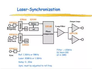
Laser synchronization D.J. Jones et al., Rev. Sci. Instruments, 73, 2843 (2002). time (sec) • two independent psec Mira 900-P (Coherent) lasers • PLLs at 80 MHz (n=1) and 14 GHz (n=175) • Sub-femtosecond timing jitter has been demonstrated between two mode-locked Ti:sapphire lasers • Limit is electronic noise (under favorable conditions)
Sophisticated laser systems are an integral component of an FEL facility Laser oscillator Laser oscillator Laser oscillator Laser oscillator Amplifier & conditioning Amplifier & conditioning Amplifier & conditioning Amplifier & conditioning Spatial profiling Amplitude control Multiply Amplifier Pulse shaping Laser oscillator FEL seed lasers Multiple beamline endstation lasers Photocathode laser
Lasers may be synchronized to a common master oscillator Laser oscillator Laser oscillator Laser oscillator Laser oscillator Amplifier & conditioning Amplifier & conditioning Amplifier & conditioning Amplifier & conditioning Spatial profiling Amplitude control Multiply Amplifier Pulse shaping Laser oscillator FEL seed lasers Laser master oscillator Multiple beamline endstation lasers Photocathode laser
rf systems need to be synchronized to a common master oscillator Laser oscillator Laser oscillator Laser oscillator Laser oscillator Amplifier & conditioning Amplifier & conditioning Amplifier & conditioning Amplifier & conditioning Spatial profiling ~ Amplitude control Multiply Amplifier Pulse shaping Laser oscillator FEL seed lasers Laser master oscillator Multiple beamline endstation lasers Photocathode laser
rf signals for the accelerator may also be derived from the laser master oscillator ~ Laser oscillator Laser oscillator Laser oscillator Laser oscillator Amplifier & conditioning Amplifier & conditioning Amplifier & conditioning Amplifier & conditioning ~ ~ ~ ~ ~ ~ Spatial profiling Amplitude control Multiply Amplifier Pulse shaping Laser oscillator FEL seed lasers Laser master oscillator Multiple beamline endstation lasers Photocathode laser Accelerator RF signals
rf photocathode laser 150 200 250 300 350 0 20 40 60 80 100 120 140 160 140 Vertical lineout 120 File: cc120605, RMS length = 1.07 ps 100 0.4 80 0.35 60 0.3 UV Power (V) 40 0.25 0.2 20 0.15 0 Horizontal lineout 0.1 250 300 350 400 450 0.05 0 -3 -2 -1 0 1 2 3 4 5 Time (ps) UV pulse time profile • UV pulse on cathode • W. S. Graves, MIT-Bates (DUV FEL, Brookhaven)
rf photocathode laser UV pulse time profile File: cc120605, RMS length = 1.07 ps 0.4 0.35 0.3 UV Power (V) 0.25 File: phiminusg, FWHM = 0.474 ps 0.2 700 0.15 600 0.1 Tail Head 500 20 0.05 40 400 0 Current (A) 60 -3 -2 -1 0 1 2 3 4 5 80 Time (ps) 300 100 200 120 140 100 160 0 180 0 0.2 0.8 1 1.4 0.4 0.6 1.2 200 50 100 150 200 250 300 350 400 Time (ps) Bunch production, acceleration, and compression • UV pulse on cathode • Non-uniformity exacerbates space-charge effects • Temporal non-uniformity induces micro-bunching • W. S. Graves, MIT-Bates (DUV FEL, Brookhaven)
Laser pulse shaping influences the emitted electron bunch RF from master oscillator Ti:sapphire Oscillator 100 fs, 2 nJ <0.5 ps jitter Q-switched Nd:YAG (2w) Ti:sapphire Regenerative Amplifier Pulse Shaper grating stretcher grating compressor 2w, 3w >1 mJ, 800 nm, 10 kHz Pulse Shaper (A.M. Weiner) Dazzler - FastLite Inc. acousto-optic dispersive filter spectral filter (computer controlled) - spatial light modulator - acousto-optic modulator (P. Tournois et al.) TeO2 crystal acoustic wave (computer programmable) - spectral amplitude - temporal phase photo- switch Deformable mirror polarizer Pockels Cell Pulse Amplitude Stabilizer Patent:: LLNL (R. Wilcox)
Laser-driven photocathode - one of the many laser systems H. Tomizawa, JASRI R. Cross, J. Crane, LLNL • Need high reliability • Integrated systems • “hot spare” system attractive • Develop techniques for pulse shaping
rf gun phase and amplitude • Cathode • Cs2Te • Laser • 1 µJ, 35 ps, 10 kHz, 266 nm • Spatial and temporal control to provide low-emittance electron bunches • RF field • 64 MVm-1 at cathode • LUX rf gun concept as an example • Assume 5% of bunch length (1 psec) jitter • Primary drivers are launch phase, cell 1 gradient and bunch charge (laser intensity) • Assumed uncorrelated disturbances: three most significant parameter tolerances are (rms values): • Launch phase: 0.43 degree • Cell 1 gradient: 1.4% variation • Bunch charge: 36% variation
Nominal LCLS Linac Parameters for 1.5-Å FEL Single bunch, 1-nC charge, 1.2-mm slice emittance, 120-Hz repetition rate… 250 MeV z 0.19 mm 1.6 % 4.54 GeV z 0.022 mm 0.71 % 14.1 GeV z 0.022 mm 0.01 % 6 MeV z 0.83 mm 0.05 % 135 MeV z 0.83 mm 0.10 % Linac-X L =0.6 m rf= -160 rf gun Linac-1 L 9 m rf -25° Linac-2 L 330 m rf -41° Linac-3 L 550 m rf -10° new Linac-0 L =6 m undulator L =130 m 21-1b 21-1d 21-3b 24-6d 25-1a 30-8c X ...existing linac BC-1 L 6 m R56 -39 mm BC-2 L 22 m R56 -25 mm DL-1 L 12 m R56 0 LTU L =275 m R56 0 research yard SLAC linac tunnel (RF phase: frf= 0 is at accelerating crest) P. Emma, SLAC
Jitter tolerance budget for LCLS based on the many sensitivities Jitter simulation, tracking 105 particles 2000 times, where each run is randomized in its 12 main rf-parameters according to the tolerance budget LCLS Jitter Tolerance Levels in the LCLS X- X-band …and test the budget with jitter simulations sz jitter = 14 % rms rmsDt-jitter = 109 fs • P. Emma, SLAC
SASE FEL output • The SASE FEL process arises from noise Saturation Half way along undulator Radiation intensity build-up along undulator http://www.roma1.infn.it/exp/xfel/SaseXfelPrinciples/Sasexfelprinciples.pdf
Slit spoiler defines radiating region of bunch 0.1 mm (300 fs) rms Easy access to time coordinate along bunch 50 mm x, horizontal pos. (mm) 2.6 mm rms z, longitudinal position (mm) LCLS BC2 bunch compressor chicane (similar in other machines) Paul Emma, SLAC
Add thin slotted foil in center of chicane BEFORE FOIL 1-mm emittance AFTER FOIL 5-mm emittance 1-mm emittance Paul Emma, SLAC
Timing determination from Electro Optic sampling -developing techniques at the SPPS A. Cavalieri Principle of temporal-spatial correlation single pulse Line image camera EO xtal analyzer polarizer Er width centroid 30 seconds, 300 pulses: sz = 530 fs ± 56 fs rms Dt = 300 fs rms
ESASE - Enhanced Self-Amplified Spontaneous Emission SASE Bunching Modulation Acceleration A. Zholents - Wednesday
70 as lL=800 nm Enhanced Self-Amplified Spontaneous Emission P0= 235 GW With a duty factor = 40, Paverage~ 6 GW x-ray macropulse • Each micro-pulse is temporally coherent and Fourier transform limited • Carrier phase is random from micro-pulse to micro-pulse • Pulse train is synchronized to the modulating laser
Harmonic generation scheme -coherent source of soft x-rays energy -p p phase • Developed and demonstrated by L.-H. Yu et al, BNL e- bunch radiator modulator laser pulse bunching chicane e-beam phase space: Input Output np -np In a downstream undulator resonant at l0/n, bunched beam strongly radiates at harmonic via coherent spontaneous emission Energy-modulate e-beam in undulator via FEL resonance with coherent input radiation Dispersive section strongly increases bunching at fundamental wavelength and at higher harmonics L.-H. Yu et al, “High-Gain Harmonic-Generation Free-Electron Laser”, Science 289 932-934 (2000) L.H. Yu et al., "First Ultraviolet High Gain Harmonic-Generation Free Electron Laser", Phys. Rev. Let. Vol 91, No. 7, (2003)
Cascaded harmonic generation scheme seed laser pulse disrupted region radiator radiator modulator modulator head tail Low e electron pulse Unperturbed electrons Delay bunch in micro-orbit-bump (~50 mm) seed laser pulse 3rd - 5th harmonic radiator 3rd - 5thharmonic radiator modulator modulator
User has control of the FEL x-ray output properties through the seed laser x-ray undulator harmonic laser seed pulse undulator undulator e-beam n undulator stages • OPA provides controlled optical seed for the free electron laser • Wavelength tunable • 190-250 nm • Pulse duration variable • 10-200 fs • Pulse energy • 10-25 µJ • Pulse repetition rate • 10 kHz • Endstation lasers seeded by or synchronized to Ti:sapphire oscillator • Tight synchronization <20 fs Q-switched Nd:YAG (2w) Ti:sapphire Oscillator <100 fs, 2 nJ <50 fs jitter Optical Parametric Amplifier Ti:sapphire Regenerative Amplifier grating compressor grating stretcher >10% conv. efficiency ~1 mJ, 800 nm, 10 kHz RF derived from optical from master oscillator Endstation synch.
Seeding with XUV from high harmonics in a gas jet (HHG) 67.5eV 25.5eV 45 39 29 25 17 Harmonic order • Coherent EUV generated up to ~ 550 eV • R. Bartels et al, Science 297, 376 (2002), Nature 406, 164 (2000) Gas jet Harmonic emission E field 0 5 10 15 20 25 30 Time(fs) I. Christov et al, PRL 78, 1251, (1997) J. Zhou et al, PRL 76(5), 752-755 (1996) H. Kapteyn, JILA/Uni. Colorado/NIST
Seeding multiple cascades from a single electron bunch allows 10 kHz operation in LUX concept FEL optical pulses e-beam • Optical pulses overlap different part of bunch for each beamline • Timing jitter influences number of cascades that can be served by a single bunch • CSR effects in the arcs introduce ~ few fs jitter for ~ few % charge variation
Laser-manipulation produces attosecond x-ray pulses in harmonic cascade FEL spectral broadening and pulse compression 800 nm e-beam e-beam 2 nm light from FEL two period wiggler tuned for FEL interaction at 800 nm time delay chicane harmonic-cascade FEL 1 nm coherent radiation dump e-beam chicane-buncher 2 nm modulator end station 1 nm radiator end station A. Zholents, W. Fawley, “Proposal for Intense Attosecond Radiation from an X-Ray Free-Electron Laser”, Phys. Rev. Lett. 92, 224801 (2004)
Ultrafast x-ray pulses by electron bunch manipulation and x-ray compression RF deflecting cavity Electron trajectory in 2 ps bunch ~ 50 fs 2 ps
Synchronize deflecting cavities and pump laser for hard x-ray production RF x-ray pulse compression asymmetric Bragg x-tals Dt Low-noise Amp 3.9 GHz Dy crab cavity 3.9 GHz Master Oscillator Laser laser pulse Dy x-rays electron bunch Dt Dt • Synchronization dependent on phase of deflecting cavity • Phase lock to master oscillator • Fast feedback systems around scrf • Extend frequency response of the system
Typical end station concept Linac x-ray pulse End station Laser master oscillator pulse Laser and delay lines Pulse diagnostics Modelocked Oscillator Precisely timed laser and linac x-ray pulses ~ 10 m • Active laser synchronization • Independent oscillators at each endstation • Complete independence of endstation lasers • Wavelength, pulse duration, timing, repetition rate etc.
l/4 PC PC Beamline endstation lasers chirped-pulse amplification Q-switched Nd:YAG (2w) Ti:sapphire Oscillator <100 fs, 2 nJ <50 fs jitter Ti:sapphire Regenerative Amplifier Optical Parametric Amplifier grating compressor grating stretcher >1 mJ, 800 nm, 10 kHz RF derived from optical master oscillator typical regenerative amplifier ~20 passes DL=1 µm (Dt=66 fs) • interferometric stabilization • cross-correlate with oscillator (compress first) • temperature stabilize (Zerodur or super-invar)
All-optical timing system to achieve synchronization between laser pump and x-ray probe Master Oscillator Laser FEL Seed Laser RF cavity Optical fiber distribution network FEL Seed Laser Multiple Beamline Endstation Lasers Linac RF Photo Injector Laser • Laser-based timing system • Stabilized fiber distribution system • Interconnected laser systems • Active synchronization • Passive seeding • rf signal generation • 20–50 fs synchronization
Timing distribution L~100 m Master Oscillator cw reference laser interferometer Master Oscillator Agilent 5501B 210-9 one hour (Dl/l) 210-8 lifetime Path Length Control DL= 2 mm Dt= 7 fs cw reference laser interferometer position detector EDFA (fiber amp) PZT control path length position detector free-space system (in vacuum) Beamline 1 fiber-based system EDFA (fiber amp) Beamline 1 Beamline 2 Beamline 2
Timing distribution - fiber systems developed fro distribution of frequency standards L~100 m Master Oscillator Agilent 5501B 210-9 one hour (Dl/l) 210-8 lifetime Path Length Control DL= 2 mm Dt= 7 fs cw reference laser interferometer EDFA (fiber amp) PZT control path length fiber-based system EDFA (fiber amp) Beamline 1 Beamline 2 D. Jones, UCB/JILA Mixer/amplifier noise floor
Modelocked fiber laser oscillatorrf stabilized 17 dBm mixer RF Clock 1.3/n GHz f 1/Trep 28 dB AMP BPF 1.3 GHz LPF Trep Amplifier Modelocked Laser 1.3 GHz error signal Modelocked Fiber Laser Oscillator – RF Stabilized • Phase-lock all lasers to master oscillator • Derive rf signals from laser oscillator • Fast feedback to provide local control of accelerator rf systems • Synchronization 10’s fs
SummaryLasers, timing,and synchronization • Laser systems under development at many institutions • Applications for improved light-source operations • Photocathode laser, timing system master oscillator, FEL seed laser, endstation pump laser • Manipulation of e- beam by laser has great potential • HHG power increasing, wavelength decreasing • Ultra-stable timing systems with optical fiber distribution systems under development • Application of techniques to accelerator environments and requirements is to be demonstrated • 10’s fs synchronization seems achievable