Download
1 / 6
70 likes | 80 Views
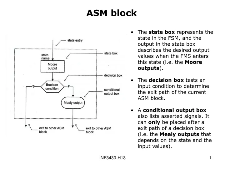
The state box represents the state in the FSM, and the output in the state box describes the desired output values when the FMS enters this state (i.e. the Moore outputs ). The decision box tests an input condition to determine the exit path of the current ASM block.

E N D
The state box represents the state in the FSM, and the output in the state box describes the desired output values when the FMS enters this state (i.e. the Moore outputs). • The decision box tests an input condition to determine the exit path of the current ASM block. • A conditional output box also lists asserted signals. It can only be placed after a exit path of a decision box (i.e. the Mealy outputs that depends on the state and the input values). ASM block INF3430-H13
ASM Chart Example 1 • Note that the conditional output box can only be placed after an exit path of a decision box. • <= is used for assigning signal values in the figure instead of = used in Zwolinski. • Use <- for register operations! INF3430-H13
ASM Chart Example 2 INF3430-H13
For a given input combination, there is one unique exit path from thecurrent ASM block. • The exit pathof an ASM block must always lead to a state box. The state boxcan be the state boxofthecurrent ASM block or ofanother ASM block. Two ASM FSM rules apply INF3430-H13
Common Errors in ASM Charts • The case to the left violates rule one since it is two exit paths if a and b are both ‘1’, and there is no exit path if a and b is both ‘0’. • The case to the right violates the first rule since there is no exit path when the condition in the decision box is false. INF3430-H13
Violates the second rule. • The second rule essentially states that the decision boxes and conditional output boxes are associated with a single ASM block and cannot be shared by other ASM blocks. Common Errors in ASM Charts continue INF3430-H13