Download
1 / 22
220 likes | 321 Views
Digital Child Project : Numerical Model Development Part 2. Mechanical Engineering University of Alabama at Birmingham. 3 rd Annual Scientific Symposium SCIB, UAB, Birmingham, Alabama December 13-14, 2006.

E N D
Digital Child Project : Numerical Model Development Part 2 Mechanical Engineering University of Alabama at Birmingham 3rd Annual Scientific Symposium SCIB, UAB, Birmingham, Alabama December 13-14, 2006
UAB - Research Team PI : Bharat Soni, PhD David Littlefield, PhD: Computational modeling & simulation Jong-Eun Kim, PhD - Simulation and optimization Zuoping Li, PhD - FE modeling Young-Ho Kim, PhD- FE modeling Alan Shih, PhD: Enabling technologies Yasushi Ito, PhD - 3D mesh generation Corey Shum - Medical image process Doug Ross - Software Development & CAGD Mark Dillavou - Software Development Collaboration with Wayne State University
ME@UAB Expertise HPC HFS 1.5+ TerFlops
ME@UAB - Infrastructure 1.5 + TeraFlop – 512 Processors – Shared UAB HPC Facility Stereoscopic & High Resolution Visualization & Virtual Reality Environment
Objective and Tasks Objective:Develop age-dependent finite element models for children Tasks : • Mesh Generation: Develop a set of algorithms for generation of triangular/quadrilateral and tetrahedral/hexahedral elements • Develop FE meshes of children aged 3, 6 and 10 years based on surface geometry provided by WSU • Assure mesh quality maintaining geometric fidelity • Perform Simulations to further validate mesh quality • Material Properties - Identify material constitutive laws and develop algorithms to estimate material constants • Develop component models - Shared repository with other SCIB consortium member institutions
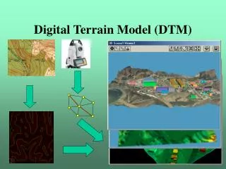
Progress – Tetrahedral Meshing (Task (a)) Medical image (CT, MRI) Image processing (ITK, VTK) Surface Mesh (Direct advancing front method) (Modified decimation method) Volume Mesh (Advancing front-based tetrahedral meshing) Geometry data from Biomechanics European Lab. Belgium
Progress – Tetrahedral Meshing Test Case Human head/brain model http://www.bic.mni.mcgill.ca/brainweb/
Progress – Hexahedral Mesh Generation Motivation: • Tetrahedral (triangular) mesh - excellent for visualization, but not favorable to computational analyses •Need an efficient algorithm for hexahedral (quadrilateral) mesh Algorithm development : • Converting triangulated surface mesh into quadrilateral elements Quality control : Different levels of triangular-to-quadrilateral conversion
Progress – Hexahedral Mesh Generation Octree based Algorithm Original triangular surface mesh All-hex volume mesh After conforming to the boundary of the geometry • Robust approach for arbitrary complex geometries • Challenges in quality and density of meshes
Progress – Hexahedral Mesh Generation Hexahedral Mesh Generation using Octree - Challenges • Boundary surface recovery • Nodes are projected onto the original surface • Invalid or low-quality hexahedra can easily be created • Buffer layers are needed to avoid creating invalid hexahedra – not easy to maintain the interface of two adjacent materials • Mesh density • Limited adaptivity to local geometrical features Boundary Buffer layer
Progress – Task (d) Simulation Examples • Children Geometry/Surface Data – Not Ready Yet! (WSU & UAB Children's Hospital – applied for IRB approval) • Simulations animal models (color index : von-Mises stress) Mouse skull impact test (Impact: steel, 0.15 lb, 10 mph)
Experiments Modeling & Simulation Validation Computational Injury Biomechanics Human Pelvis Side Impact Experiments & Simulation Objectives : To investigate the injury mechanism of human pelvis exposed to high-speed impact environments through computational modeling, simulation and experiments Comparison of biomechanical responses from simulation with experimental results Drop mass Load cell 3D pelvis solid model created from CT scans at ETLab Ring of markers Contralateral support Finite element side impact simulation Drop tower impact testing Enabling Technology Laboratory
Progress – Task (d) Simulation Examples (Cont.) • Simulations with adult head/brain and lung models Impact to a rigid wall with 20 mph Stress propagation in brain Airbag model from NCAC Effect of an airbag deployment Lung model and respiration (Head speed 60 mph) (Lung volume change due to Intrapleural pressure )
Progress – Task (e) A Method to Identify Material Constants Motivation: • Efforts on pediatric properties and responses - very limited due to difficulties in getting pediatric cadavers • The material properties of pediatric bones and tissues - much different from those of adults • Scaling of adult data has been used - not fully validated • Need to find pediatric properties directly using available test data Algorithm development : • Simulation/optimization-based material property identification
Progress – Task (e) A Method to Identify Material Constants – Flow Chart Assign material constitutive models to each component (linear elastic, nonlinear viscoelastic, hyperelastic, etc.) Estimate material constants and their ranges (elastic modulus, coefficients of strain energy density functions and viscoelastic behavior, etc.) Apply optimization technique (Surrogate-based) (to obtain the most favorable material constant by minimizing the differences between experimental and simulation results) Perform static and dynamic finite element analyses (with boundary, initial, and loading conditions in agreement with those used in the experimental setup)
Progress – Task (e) Surrogate-based Optimization Scheme DACE(Design and Analysis of Computer Experiments) Selected sets of design variables Analysis Construct surrogate model (Metamodeling) Optimizer
Progress – Task (e) Apply the Optimization Scheme to Material Identification : A Test Case In-vivo material property of human common femoral artery • Obtain a most favorable material constant set in Mooney-Rivlin hyper elastic model • Agreement with a pressure-diameter (P-D) curve measured in Ahlgren et al. (2001) Assign material constitutive models to each component Select Mooney-Rivlin hyper elastic model (strain energy potential) Estimate material constants and their ranges Apply optimization technique Perform static and dynamic finite element analyses Simulation : Diameter change under an internal pressure
Progress – Task (e) Apply the Optimization Scheme to Material Identification : A Test Case (result) Surrogate-based optimization to minimize the discrepancy of P-D curves from experiment and simulation Apply optimization technique P-D curves with optimal material constants Latin hypercube sampling (20 samples) Second-order polynomial approximation Optimizer : Method of feasible direction Male based on a table of simulation results Male Female Female
Progress – Task (e) A Method to Identify Material Constants – Near Future Work Example: Age-dependent material properties of soft tissues (Ligaments of cervical spine) • Material constants for a hyper elastic model • Experimental results using pediatric cadavers (Ouyang et al., 2005) & SCIB members • Develop biofidelic FE models from medical images • Model five ligaments (ALL, PLL, ISL, LF, CL) by : - Beam elements - Transversely isotropic hyper elastic constitutive model • Perform computational tension, compression, and flexion and extension bending tests to find the optimal constants • Include neck muscles
Progress – Task (e) A Method to Identify Material Constants – Future Work • FE Calculations performed with ALEAS (in-house research CSM code) • Advanced high-fidelity algorithms that do not require artificial stabilization (NO hourglass controls or pressure stabilization are used) • Arbitrary Lagrangian-Eulerian formulation (run in Lagrangian mode) • Numerical errors precisely controlled with error estimation and mesh adaptation algorithms • Improve the optimization code to include modules for : - Handling multiobjective functions - Multilevel decomposition - Interfacing with simulation codes - User-friendly interface - User manual
Progress – Task (e) • Apply it to obtain age-dependent pediatric material properties with child FE models • Pursue child experimental data from SCIB member institutes • Use ALEAS for multi-continuum scale modeling of TBI1 • capture localized deformations arising from heterogeneity on microscale • Improved geometrical and constitutive modeling of cranial membranes and brain tissues • High fidelity numerical approach with precise error control • 1Work in progress - Kulathu Dissertation (Advisor – Littlefield)
Acknowledgement Support from Southern Consortium for Injury Biomechanics (SCIB) & Collaboration with Wayne State University and SCIB members