Download
1 / 45
460 likes | 616 Views
A status report on the HMPID DCS. The HMPID in ALICE ; The HMPID Detector Control System: Hardware and Software Architecture; Investigated solutions for the HV-LV power supplies and market survey; Overview on the components of the HMPID Control system:

E N D
A status report on the HMPID DCS • The HMPID in ALICE ; • The HMPID Detector Control System: Hardware and Software Architecture; • Investigated solutions for the HV-LV power supplies and market survey; • Overview on the components of the HMPID Control system: • The (CAEN SY1527) HV C.S. in the PVSS environment; • A custom C.S. for the EUTRON LV units; • A C.S. prototype for the Liquid re-circulation apparatus; • Next steps………... • Expectation from the JCOP and CCTeam
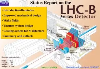
HMPID layout on the Spaceframe The ALICE Particle Identification system (PID) is based on three detectors covering the central ALICE barrel (ITS, TPC and TOF), and one single-arm detector: the High-Momentum Particle IDentification (HMPID). The HMPID is based on a Ring Imaging Cherenkov dertector, it is devoted to the identification of the high-momentum pions, kaons and protons in the range 1 - 3 GeV/c.
RICH detector: basic elements The RICH detector consists of a vessel containing C6F14 as liquid radiator and a multiwire proportional chamber with a CsI segmented photo-cathode. When a relativistic charged particle cross the radiator faster then the phase velocity of light in that media, then few tens of Cherenkov photons are emitted and converted on the CsI film. The emission angle of photons is related to the particle velocity v according to cosq = 1/nb where b=v/c. If the particle momentum is known then its identification can be done, with this detector layout, in the range 1-4 GeV/c 3
Cherenkov liquid radiator Sub-system Physical parameters Sub-system Low Voltage Sub-system High Voltage Sub-system Gas Sub-system Basic elements of the HMPID DCS An artistic view of the hardware! Supervisory Layer NT Workstation Control & Physical layer CAEN SY1527 PLC S7 PLC S7 PLC S7 ??
The Software Architecture of the HMPID DCS LPC = Local Process Control HMI = Human Machine Interface FSM = Finite State Machine DIM = Distributed Information Manager (CERN) SMI = State Management Interface (CERN) OPC = OLE for Process Control (Microsoft) DCOM = Distributed Component Object Model (Microsoft)
Working in Progress on….. Evaluation of a preliminary asset of Data Point for the HV Sub-System (the physical device SY1527 is not yet available in the present framework This OPC serv. doesn’t run properly in PVSS and it doesn’t allow the grouping managment! CAEN will issue the version 1.1 on Aug. 2001. Some Detector Oriented panels in PVSS for Monitoring and Setting are already under test Perfectly working ! Preliminary representation of the LCS via GRAFCET. The related Instruction List is already in Debugging Phase Preliminary GRAFCET and Instruction List in Test Phase
Operational classes of the HMPID DCS prototype (Preliminary definition) • CONFIGURATION • MONITORING • OPERATIVE STATUS • DEBUGGING • checks the Permission Access Policy • provides Panels to Load, Edit and Save Sub-Detector Configuration Parameters • verifies the selected detector Configuration • Logging of the selected Configurations • provides Panels to display/modify Actual/Trend/Historical Parameters • verifies that the Parameters are in the ranges • provides Alarms management • provides Logbook facilities • accept commands from the supervisory layer • check the Permission Action Policy • control and synchronise the sequence of operations • provides Local Process Control procedures • provides tools and facilities for Sub-Detector debugging: dummy Trigger equipment, local data taking, data base management, …
Investigated solutions and market survey for the HV-LV sub-systems
LV-HV Sub-systemsCAEN solution:Resulting detector segmentation MCM6 MCM1 MCM2 MCM4 MCM5 MCM3 MCM8 MCM9 MCM10 MCM11 MCM12 MCM7 ADC4 ADC3 ADC2 ADC1 FEE FEE FEE FEE 1 FEE 2 FEE 4 FEE 5 FEE 7 FEE 8 3 6 9 H3 H6 H9 H4 H5 H8 H1 H7 H2 12 MCM Segments 4 ADC Segment 9 FEE Segments, 180 (120) GASSIPLEX each 9 HV Segments, 36 (24) wires each, this requires a grouping of 12 sense wires Power requirements/segment V A W FEE+ +2.8 4.8 (3.2) 13.5 (9.0) FEE- -2.8 5.0 (3.4) 14.0 (9.5) ADC+ +5 2.0 10.0 ADC- -5 2.0 10.0 MCM +5 3.0 15.0 7 x HMPID MODULE 3 x CAEN SY1527(TCP/IP protocol) Boards: 9 x A1517 3V-6A(prot. by the end of 6/2001) 11 x A1518 5V-3.6A(.. by the end of6/2001) 6 x A1821A 3kV(Delivered and test under way)
Layout of the CAEN solution Rear view Front view
2 MCM Segments 1 ADC Segment 6 FEE Segments, 480 GASS. each 6 HV Segments, 48 wires each MCM2 MCM1 ADC1a ADC1b FEE 6 FEE 5 FEE 1 FEE 3 FEE 4 FEE 2 H3 H4 H2 H6 H5 H1 LV-HV Sub-systemsWIENER or EUTRON based solution: assumed detector segmentation Power requirements for each segment V A W FEE+ +2.8 5.9 17.8 FEE- -2.8 6.8. 18.7 ADCa+b +5 8.0 40.0 ADCa+b -5 8.0 40.0 MCM +5 18.0 90.0 For both these solutions, the HV PS is still based on the CAEN SY1527
The Master Power Box can operate via • RS232 up 8 slave crates • CANbus up to 127 crate • TCP/IP offers performance for larger numbers of channels. FEE : 42 segments x 2 polarity 84 modules (2.8Vx12.7A=36.5W) MCM : 14 segment 14 modules (+5Vx18A=90W) ADC : 7 segments x 2 polarity 14 modules ( 5Vx16A=80W) Layout of the WIENER LV units Master Power Box Master power 3U box: Max DC Power/box =2.5 KW Up to 12 PL600 modules/box One module consist of one floating ch. 2..7V - 25A max 175W
EUTRON PS Units 3 x EUTRON BVD 720S 0..8 v 25 A 1 x EUTRON BVD 1500S 0..8 v 50 A PLC SIEMENS S7300 Connecting and sensing Board TO HMPID MODULES Layout of EUTRON-PLC devices For the EUTRON solution the power switching and sensing of each LV channel are based on a Siemens PLC system (relays and ADC modules) and a custom sensing board. This solution requires a control program developed ad hoc by the user.
First cost estimation(cables and connectors not included) • CAEN HV-LV • EUTRON LV + CAEN HV (PLC software development not included) • WIENER+ CAEN HV LV HV € CHF € CHF 111.350 172.500 23.150 36.000 66.200 102.500 30.100 46.700 56.800 88.000 30.100 46.700
The EUTRON-PLC Control System • Requirements list; • The control system as a Finite State Machine; (bubble chart) • Apparatus layout and technical specifications of the sensing board; • the PLC readout software. E. Carrone,
The Requirements list It is intended to specify all the procedures to operate properly the LV power supply units while connected to the FE electronics. An incomplete example could be: • FEE LV switching ON: since the FEE requires ±2.8 V then both these polarities must be supplied contemporary, • FEE LV switching OFF: before a FEE segments is switched OFF, the facing HV segment (see St.Rep3 at http://richpc2.ba.infn.it) must be switched OFF. This sequence is mandatory to prevent FEE breakdowns due to charge accumulation on the MWPC cathode pads. (In fact the ground reference to the MWPC sense wires is ensured trough the FE electronics, then the low voltage at the corresponding FE electronics segment must be applied before the HV segment is switched ON); • Current and voltage ranges: Vload Iload must be in the admissible range: Vmin < Vload < Vmax, Imin < Iload < Imax. If Iload > Imax then the corresponding HV-LV segments must be automatically switched OFF according to FEE LV switching OFF sequence • Alarms handling … • … E. Carrone,
The control system as a Finite State Machine: state definition Taking into account the requirement list and how to properly operates the EUTRON units, the following “states” have been defined: • OFF ( P.S. in Standby, relays OFF and Vout=0) • Calibration (reading Voutput from units) • Configuration (FEE segment selection) • Standby (LV system in STBY status) • ON (Ready For Physics: P.S. STBY removed, check ofCurrent/Voltage values) E. Carrone,
Alarm Condition COMMANDS COMMANDS START START CALIBRATE RUN START CONFIGURE FILL CONFIGURE STOP PURGE SUSPEND STOP FEED MAN CONF RESET RESET STOP STBY CAL SUSPEND FEED CALIBRATE STATES OFF CALibration ON ALARM OFF CONFiguration RESET STBY Standby ON Ready ALARM LV C.S. representation When the ON state is active Iload and Vload are monitored on all the active FEE segments. If one of these values is out of range then the relevant FEE segment is switched OFF and the HV system is contemporary notified to switch OFF the corresponding HV segment. During the transition ON->STBY the HV status must be checked and if it is HV-ON then the LV C.S. must kill the HV system. STATES OFF Stop Running Filling Ready LV: the bubble chart representation E. Carrone,
Power Supply Dummy resistive Load NT Workstation CH1/2 Power line Sensing Board Set and reading PS Vout Vload sensing line Ethernet Iload sensing line from-to PLC relays Siemens S300 PLC Apparatus Layout In order to split the PS current into several channels, each one connected to one FFE segment, a PLC relays module is used. The Vload-Iload measurement is based on a sensing board read out via 8CH ADC module. Power Supply: EUTRON BVD720S, 0-8V, 0-25 A. PLC: Siemens S300 Analog Inputs 8 x 12 bit. E. Carrone,
Vs - Vs + Sensing Board E. Carrone,
Signal Conditioning The input stage of the ADC accepts the max Common Mode Voltage UCM= 2.5V. This imposes a Vsensing attenuation via a resistive net (UCM= (Vin+Vo)/2 3.9 V) . THE NET RESISTOR æ ö æ ö R 2 R 4 R 4 = - = - + ç ÷ ç ÷ V V V V V + + - + sr s s in sen sin g + + + R 1 R 2 R 3 R 4 R 3 R 4 è ø è ø + ( ) R 4 R 3 R 4 = + Þ = - V V V V V V + + sr ped sen sin g sen sin g sr ped + R 3 R 4 R 4 In order to measure the Vped, Rsens has been put in short circuit (Vsensing=0) and this resulted in Vped=5 mV. To evaluate the Ucm attenuation factor A= R4/(R3+R4), Vsr and Vsensing have been measured and it resulted in A=0.1325: Vsensing = (Vsr - Vped)/A Finally Iload = Vsensing / Rsens With the ADC LSB of 22.4 mV in the range +-80mV, a current sensitivity d=LSB/A*Rs= 2.8 mA on the Iload is achieved. This allows the C.S. to detect the single FEE chip failure which drains 45 mA per polarity. E. Carrone,
Process Input Word ADC “brute” value PIW 288 “V sensing + ADC” --- DEC 8872 PIW 290 “V sensing – ADC” --- DEC -14440 PIW 292 “V load + ADC” --- DEC 15496 PIW 294 “V load – ADC” --- DEC -15496 MD 100 "I load +“ --- REAL 3.737275 MD 108 "I load -“ --- REAL -4.101968 MD 132 "V load +“ --- REAL 2.802372 MD 124 "V load -“ --- REAL -2.802372 MD 20 "V sensing + input ADC“ --- REAL 25.67129 MD 28 "V sensing - input ADC“ --- REAL -41.7824 [V] [A] Memory Double Word [mV] PLC VAT (Variable Table) E. Carrone,
PLC Instruction List NETWORK TITLE =Sensing Current CH + AN Q 4.1; S Q 4.1; AN Q 4.2; S Q 4.2; AN Q 4.0; S Q 4.0; AN Q 4.3; S Q 4.3; L PIW 288; ITD ; DTR ; L 2.893518e-003; *R ; T “V sensing + input ADC"; L 5.000000e+000; L “V sensing + input ADC"; +R ; T MD 68; L MD 68; L 7.566840e+000; *R ; T MD 84; L MD 84; L 6.210000e+001; /R ; T "I load +"; Relays switches ADC reading value [mV] Integer: 16 bit 32 bit Pedestal offset Integer 32 bit IEEE-FP 32 bit 1/A where A=attenuation factor V I Conversion E. Carrone,
Control System for the CAEN SY1527 in the PVSS environment. The Configuration Program A devoted program reads from a file the HV sub-system configuration ( # HMPID modules, HVsegment/module) and creates the DataPoint data base in the PVSS environment. These data points are automatically created according to the specified variables (Crate/Board/Channel) of the CAEN OPC Server and it sets a link between the OPC variable addresses and the PVSS data base.
Monitoring panel of the HMPID HV System Alarm condition Link to the Monitoring Panel of SY1527 Link to the Monitoring Panel of the HV segment Segment disabled “Burned-out” Segment Link to the Enable/Disable Panel Link to the Channel Configure Panel
Monitoring panel of the HV Segment (when the CAEN SY1527 OPC serv. Is running!) Channel settings Channel Status HV-ON Channel Name Actual value of Parameters Trend display settings Trend parameter Chart
Enabling/disabling HV Segments Option for global Enable/Disable action Segment Enabled Segment Disabled Exit
HV Channel configuration Parameter Value Parameter Name Cancel all the changes Save the present configuration Exit
SY1527 Control panel Inserted board status Board description Power System Name Empty slot Crate Alarm condition Crate Front panel status Fan & Power unit Status Crate commands Crate settings
The Control system of the Liquid Circulation apparatus : from design to implementation The system description LCS as a Finite State Machine the GRAFCET representation of LCS the Object Oriented Representation Model the Local / Remote Mode switch facility the Heart Beat Signal facility LCS Control System: the Main Program Flow-Chart LCS the Instruction List v.0.1
The Liquid Circulation System … a Winner approach !!
The system description The aim of this apparatus is to re-circulate the C6F14 liquid radiator into a quartz vessel named RADIATOR in the figure. The hydrostatic pressure ensured by the position of the HEATHER with respect to the RADIATOR, keeps constant the flux. The system consist of a PUMP, three electrovalves EV_1, EV_2, EV_3 and four pressure sensors Pt_2, Pt_4, Pt_6, Pt_9. The tank, the radiator and the header are connected to a gas supply of Nitrogen, and Argon is used to activate the electrovalves just quoted before. The pump fills the HEADER which ensures the constant flux in the radiator once it has been filled.
The LCS Control System: a Finite State Machine First of all, the system is into the OFF state, all the inputs are closed and the system is into a “safety” state. A START command moves the state from OFF to “Stop”, the critical parameter are tested and the run configuration is load. The Next command is RUN that move the machine into the “Running” state, the PUMP is switched ON and the pressures are tested, during this phase the liquid fills the Header. If all the conditions are satisfy, a FILL command put the system into the “Filling” state, then start the radiator filling phase and when its level get the maximum the system moves to the “Ready” state. A PURGE command, bring the system into the “Purging” state and the radiator is made empty. When the machine is into the “Running” state a STOP command bring the system into the “Stop” state: the header is purged and the PUMP is switched OFF. The operator can also decide to run the LCS in the manual mode. In this case, he has to send a MAN command and then system is forced into the “Manual” state. All the alarm conditions puts the system into an “Alarm” state that provide the “safe mode” operation. Only a RESET command can move the system from this state. LCS: the bubble chart representation
The LCS Control System:the GRAFCET representation The NORMAL GRAFCET The MASTER GRAFCETs The GRAFCET representation of LCS consist of one Normal GRAFCET, that provides all the operations involved into the regular evolution of the system, and six Master GRAFCET, each one controlling particular functions as Alarm conditions, Break command, ecc. In red are reported the actions of the Master GRAFCET’s which force the Normal GRAFCET into a defined state. An example of GRAFCET. Transitions: a,b. States: 1,2,3. Actions: S1, S2
The LCS Control System:the Object Oriented Representation Model The Control Program running into the PLC performs the encapsulation of the entire LCS, it exports, to the upper DCS layers, one input COMMAND variable and one output STATUS variable. This variables are communicated by means of the OPC/DCOM protocol. Other two service variables perform the role of carriers for Configuration Parameters and Messages. During the “expert” and “ debugging” operative mode when the system has to allow the maximum accessibility, the LCS object export to the upper level all the internal variables in order to make visible the entire machine domain.
The LCS Control System:the Local/Remote Mode switch facility The Control Program stored into the PLC can run in a “Local Control Mode” or “Remote Control Mode”, in order to implement the facilities for debugging and development phases. In Remote Mode the system communicates by the OPC link, otherwise, in Local Mode it is connected to a front panel near the PLC. The control mode is selectable by a PLC switch.
The LCS Control System:the Heart Beat Signal facility ORGANIZATION_BLOCK "Hert Signal Generation" TITLE = "Cyclic Interrupt" //Blocco per la generazione del segnale di "Heart" del PLC. //Ad ogni richiamo viene variato lo stato della variabile heart_signal, oltre ad //incrementare un contatore. // //ATTENZIONE ! E' necessario modificare il valore dell'intervallo di richiamo //portandolo a 1000 ms. (Simatic -> Hardware -> Proprietà CPU -> Schedulazione //Orologio VERSION : 0.1 VAR_TEMP OB35_EV_CLASS : BYTE ; //Bits 0-3 = 1 (Coming event), Bits 4-7 = 1 (Event class 1) OB35_STRT_INF : BYTE ; //16#36 (OB 35 has started) OB35_PRIORITY : BYTE ; //11 (Priority of 1 is lowest) OB35_OB_NUMBR : BYTE ; //35 (Organization block 35, OB35) OB35_RESERVED_1 : BYTE ; //Reserved for system OB35_RESERVED_2 : BYTE ; //Reserved for system OB35_PHASE_OFFSET : WORD ; //Phase offset (msec) OB35_RESERVED_3 : INT ; //Reserved for system OB35_EXC_FREQ : INT ; //Frequency of execution (msec) OB35_DATE_TIME : DATE_AND_TIME ; //Date and time OB35 started END_VAR BEGIN NETWORK TITLE =Main A "heart_signal"; NOT ; = "heart_signal"; = "HEART_LED"; L "heart_signal_counter"; INC 1; T "heart_signal_counter"; END_ORGANIZATION_BLOCK Every 500 milliseconds the PLC Operating System automatically run a dedicated job, named OB35, it generates the “Heart Beat” signal, in order to indicate that the PLC is “alive” The program is shown in figure and it produces a 1 Hz blinking led with a continuos increasing counter as run timer. One or all the program variables can be exported to the upper layers of DCS by the OPC link.
The LCS Control System:the Main Program Flow-Chart • Every Scan Cycle the PLC CPU perform this actions: • Stores the status of inputs into the Process Image Memory (created by the PLC Operative System) • Tests an Interlock line that stop all the processes • Executes the signal conditioning of inputs (trends, thresholds, Boolean expressions) • Tests the Local/Remote Mode Switch • Copies the Commands Variable from the Hardware Inputs (Local) or from the OPC Buffer (Remote) • Calculates all the Boolean expressions that realize the Transition Condition of the GRAFCET • Activate the States, and perform the “entry active state actions “ • Execute all the actions related to Active States • Sends to the Outputs the values contained into the Process Image Memory (created by the PLC Operative System).
The LCS Control System:the Instruction List v.0.1 BEGIN NETWORK TITLE =Main loop Control // Verifica che lo Switch "Secure" sia ON A "secure"; JCN fine; // chiama le funzioni che preparano il ciclo CALL FB 1 , DB 1 ;// lettura degli input dal pannello o da remoto CALL FB 2 , DB 2 ;// lettura e valutazione dei pressostati NETWORK TITLE =Verifica recettività // verifica delle recettività per i MASTER A "Stato_10"; AN "Stato_1"; A "|stop"; = "TR_12"; A "Stato_12"; A "gp4giu"; O( ; AN "Stato_1"; A( ; O "gp2giu"; O "gp6giu"; O "gp9giu"; ) ; ) ; AN "STOPMODE"; = "TR_14"; A "Stato_14"; AN "Stato_1"; A "|start"; = "TR_16"; A "Stato_16"; A "|manual"; = "TR_18"; • A primary version of Instruction List has been produced • At present it is under debugging and Test phase • In the next future: • Message communication facilities • Configuration procedure • Time synchronization • Measurement of the reaction time • Exploitation of failure and breakdown events and relative PLC reaction • ...
Next steps: • Since the HMPID DCS has to be fully integrated in the ALICE DCS then a.s.a.p. an advanced version of the JCOP Framework will be available, we intend to integrate there as much as possible of the HV, LV, Liq. Rec. Sub-systems to get a first HMPID DCS prototype. Unfortunately the present version (000921) of the framework doesn’t yet include the physical device SY1527. • As soon as the CAEN SY1527 OPC server will be delivered, we intend to carry out tests on the new version (we hope equipped with the channel grouping management as we asked for to the CAEN)
Guidelines to implement HMPID Control Layer To integrate HV-LV-re_circulating control systems in the first HMPID DCS prototype, we are working on: • Design of the DCS control part as a FSM • Implementation of the control procedure as a PVSS extension in SMI++ language • Use the DIM protocol for the inter-process communication …..which means • Test the DIM – PVSS integration • Test the SMI++ language into PVSS environment • Design and implement a small control procedure for the performance evaluation • Define the architectureof the lower layers interlock
report on DIM Testing phases • DIM tools (already tested) • DIM driver for PVSS - Client Side (under test) • DIM driver for PVSS – Server Side (not yet implemented) • DIM – PVSS performance evaluation • … report on SMI++ Testing phases • Implementation and test of a control DLL into PVSS environment (done) • SMI++ language structure (done) • SMI++ Tools • Implementation and test of a control program in SMI++ • Implementation and test of a small FSM in SMI++ into PVSS environment
PVSS Control DLL DIM Driver PVSS domain PVSS Data Point DB Other PVSS domain PVSS User Interface Control Program PVSS panels User Interface The resulting DIM – SMI++ - PVSS architecture Develop Phase Run Time structure DIM DNS Server Other Application DIM protocol based FSM description SMI++ Editing Tools DIM Test Tools SMI++ source code SMI++ Traslation Tools SMI++ proxy code Visual C++ Develop Envir. PVSS External Control DLL
Expectation from the JCOP and CCTeamas conclusion • We propose the JCOP to include in the next release of the Framework an example of DCS based on the Physical Devices CAEN SY1527 and Siemens PLC. It could be a nucleus of running DCS very useful for the sub-detector DCS developers. For this specific case we are available to suggest the Control Hierarchy(how to operate correctly the HMPID HV-LV sub-systems) • The CCTeam should co-ordinate and assists the ALICE DCS developer groups and mediate specific requests with the JCOP.