Download
1 / 49
490 likes | 651 Views
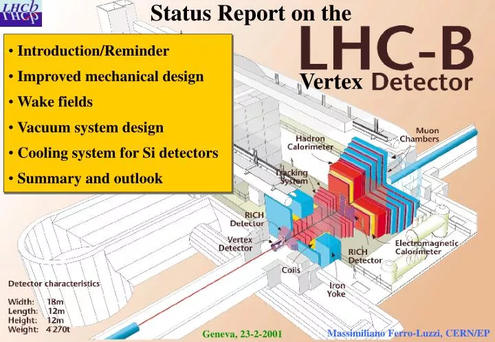
Status Report on the . Introduction/Reminder Improved mechanical design Wake fields Vacuum system design Cooling system for Si detectors Summary and outlook. Vertex. Massimiliano Ferro-Luzzi, CERN/EP. Geneva, 23-2-2001. LHCb VD - LHC machine integration issues.

E N D
Status Report on the • Introduction/Reminder • Improved mechanical design • Wake fields • Vacuum system design • Cooling system for Si detectors • Summary and outlook Vertex Massimiliano Ferro-Luzzi, CERN/EP Geneva, 23-2-2001
LHCb VD - LHC machine integration issues • The LHCb Vertex Detector system should not hamper LHC operation • Address: • vacuum issues • static and dynamic vacuum see Adriana Rossi’s presentation • calculations and test measurements • radio-frequency issues • high frequency modes, coupling impedance Z|| / n • calculations and test measurements • safety issues • define level of acceptability • perform risk analysis
Support frame “TP” Design presented at LEMIC February 2000 Bellows (22000 signal wires) Si detector Bending hinges Detector support and cooling Side flange with feedthroughs moves by 30 mm only two positions: open or closed !! Si encapsulation and center frame are not shown ! see LHCb note 99-042/VELO
Difficulties with TP design • FEA displacement studies led to a rather bulky center frame • poor sideways accessibility for (a) wake field suppressors (b) Ti evaporator insertion • System was not bakeable (the reverse was under study) • base primary vacuum pressure p1 ~ 10-8 mbar • aging of NEGs due to gas flow from VDS (?) • dynamic vacuum: struggle to get Icrit > 3.4 A • Communicating 1ary and 2ary volumes • NEGs must be regenerated after every access to Si detectors limited to ~10 cycles (?)
TP design Desired situation center frame Si detector box No room on the sides ! Side wake field suppressors Ti evaporator
Decouple access to Si detectors from access to 1ary vacuum Use ultrapure neon venting NEGs need not be baked after access to Si detector Baking up to 150 oC is possible Mount two detector halves independently use of non-standard, large-size, rectangular bellows Optimized System M. Doets, NIKHEF air 1ary vacuum 2ary vacuum
Detectors halves opened/closed in steps (remote-controlled) vert. = 10 mm, horiz. = 2x30 mm Microswitches at out position LVDTs Steel frame Alignment: 2 planes 3 points each define IP All motors, bearings, gearboxes, etc., are outside vacuum Support and motion mechanics motor chain/belt bellows 30 mm cooling/bake out 30 mm gearbox 1:40 10 mm ball spindle 16x2 linear bearing 2x
Alignment pins for reproducible coupling Reproducible positioning Outer switch positions aligned to nominal beam axis Support system
Move bellows and couplings to “closed” position Install vessel from top Align vessel to beam line Fix vessel to frame Attach bellows Vessel installation
Remove upstream flange (need 2 m access) Rectangular bellows 60 mm stroke normal 30 mm lateral 6 mm need not withstand atmospheric differential pressure Fabrication difficult and costly! Palatine, Bird, Calorstat, MB, VAT, ... Install detector housings = 2ary vacuum vessel • Install wake field suppressors and close upstream spherical flange
Detector system separated from vacuum system functionality Connect inner system (detector housing) to motion drives via side flanges Install pump-out, valves turbo pumps, damping Seals: 1ary / air: all metal 1ary / 2ary: viton & metal 2ary / air: viton & metal Complete installation of 2ary vacuum system
Install detector halves from sides Decouple detectors from flange box Tooling needed Detector half can be replaced by a dummy flange box Detector installation Detectors Flange box
Install wake field suppressors after mounting 2ary vacuum container Mount through top flanges seal with view ports ? Upstream is easier: mounted with large flange off 420 910 IP WF screens Wake field suppressors
Current design: Up/downstream suppressors are identical Material: CuBe Length: 179 mm Thickness: 100 m 16 segments Mounting to detector box is non-trivial Wake field suppressors
…continued: Segments deform differently during movement Coating needed on suppressors (?) Press-fit to beam pipe structure Anneal CuBe, deform, harden at 400o C Wake field suppressors
Wake field simulations N. van Bakel VU Amsterdam • Performed MAFIA simulations: • full tank model and smaller models • detector halves in position open and closed • compared various detector encapsulations with • different corrugation shape and depth • complex non-symmetric structures! • LHCb-99-041 “A first study of wake fields in the LHCb VD” • LHCb-99-043 “W. f. in the LHCb VD: strip shielding” • LHCb-99-044 “W. f. in the LHCb VD: alternative designs for the w. f. suppr.” • Conclusions: • Frequency domain: no problematic resonant effects • for corrugated encapsulation with corrugation depth < 20 mm • Time domain: losses are acceptable • Under study: • low frequency slope of Im(Z||) • Time-consuming and CPU intensive(ABCI & MAFIA) Thanks to: O. Brüning D. Brandt L. Vos
RF tests at NIKHEF F. Kroes, NIKHEF • Study: • Eigenmodes, short range effects, Z|| • Effect of WF screens, open/close halves • RF fields inside secondary vacuum (pick-up) • Use: • Wire method • Multiple (rotatable) loop antennas • Reference LHC pipe First 3 measured eigenmodes of empty tank: 220, 270, 320 MHz Compare to simulation with MAFIA
Vacuum system layout • Main changes since last LEMIC (february 2000): • removed conductance between 1ary and 2ary volumes • conductance: 1 l/s 10-5 l/s • reduced contamination of 1ary vacuum and NEGs • development of gravity-controlled safety valves • used in addition to pressure-switch electrically activated valves • intrinsically safe solution • decoupled air exposure of 1ary and 2ary volumes (see mech. design) • use of ultrapure neon venting procedure to preserve NEGs • bakeable system (T 150 oC) • reduces effect of several (static & dynamic) vacuum phenomena!
Vacuum system layout …continued • Unchanged since last LEMIC (february 2000): • thin separation foil between 1ary and 2ary vacuums which • does not withstand atmospheric pressure • performed extensive MC physics simulations (assess effect of material) • investigated feasibility of Beryllium option (Brush Wellman) • performed extensive FEA calculations for Al and Be • developed a gravity-controlled safety valve to protect against differential pressure increase • mixed-phase CO2 cooling system for Si detectors in 2ary vacuum
Thin vacuum foil Beryllium(1 mm thick): • FEA: max p 500 mbar* • ~500 kUS$ per container if at all feasible! • safety issues Aluminum (0.25 mm thick): • FEA: max p 15 mbar* • NIKHEF: successfully welded 100 m on 300 m • press-shaping being developed at NIKHEF • “cheap & readily” available (compared to Be) *means: irreversible deformation, no safety factor included
FEA for Al foil 0.25 mm Displacement [mm] Assumed annealed Al yield strength of 40 MPa (typical Al ~ 40…250 MPa) Max p 15 mbar (irreversible deformation no safety factor included) By Marco Kraan, NIKHEF many more results at http://www.nikhef.nl/pub/departments/mt/projects/lhcb-vertex/
FEA for Be foil 1.0 mm Displacement [mm] Assumed S-200F hot pressed block with a yield strength of 270 MPa (SR-200 cross rolled sheet: yield strength = 340 Mpa) Max p 500 mbar (irreversible deformation no safety factor included) By Marco Kraan, NIKHEF many more results at http://www.nikhef.nl/pub/departments/mt/projects/lhcb-vertex/
Multiple scattering Main Problem: • trigger decision based on tracks displaced from primary vertex • no momentum information at this trigger stage • low-momentum particles undergo more multiple scattering fake signatures of a displaced secondary vertex performed extensive Monte Carlo simulation and analysis Result: Increasing thickness of Al foil (100250mm) reduces vertex trigger efficiency by factor ~1.2 (20% loss of good events) Other Problems: • increased background rates • increased occupancies III, 250 m foil II , 250 m foil TP, 250 m foil III, 100 m foil II , 100 m foil TP, 100 m foil Minimum bias retention 0.08 0.04 0 0 0.2 0.4 Signal efficiency
Thin vacuum foil • Labour intensive: • manufacture moulds • make foils: ~12 press/anneal cycles, etc. • Extensive prototyping program CP?! Chiel Bron
Thin vacuum foil • Increase radius (10 20 mm) to avoid folding • Crystal structure seems affected • Development tests: • Employ Al alloy with Mg • Deform at higher temperature: 150 - 200 oC • Later, vacuum tests: • microscopic holes ? (leaks) • mechanical properties: deformation pressure, rupture pressure, etc.
Mixed-phase CO2 Cooling system Phase diagram CO2 • Advantages: • Radiation hard (used in nuclear power plants) • Non toxic (conc. < 5%), non flammable • Low pressure drop in microchannel tubes • Good thermodynamic properties • Widely available at low cost • No need to recover or recycle • Principle of operation: • CO2 is used in a two-phase cooling system. • The coolant is supplied as a liquid, the heat is taken away by evaporation. • LHCb VD: in total, ~ 54 40 W of heat, each cooled by a pipe of OD=1.1mm/ID=0.9 mm. • Tested at NIKHEF: See LHCb 99-046/VELO • capacity of cooling pipe > 50 W • heat transfer coefficient between pipe and coolant > 2 W cm-2 K-1 critical point 100 solid liquid gas Pressure [bar] 10 vapor triple point 1 -80 -70 -60 -50 -40 -30 -20 -10 0 10 20 30 40 50 Temperature [°C]
CO2 Cooling system layout H. Boer Rookhuizen, NIKHEF 2ary vacuum Hall area Behind shielding wall Storage vessel Gas return (12mm) Standard refrigerator unit ~ 60 m Liquid supply (6mm) Liquid CO2 pump Cooling tubes (0.9/1.1 mm) Heat exchanger Restriction (0.85*40 mm) Needle valve(sets total flow) Pressure regul. valve (70 bar) Shutter valve
CO2 Cooling Tubes • ID = 1.1 mm, OD = 0.9 mm • vacuum brazed (no flux, no fittings) • can sustain p > 300 bar • (CO2: pequilib = 72 bar at 30 oC) • Total amount of CO2 in the system • 6 l of liquid 3 m3 of gas at STP • In the 2ary vacuum volume: • 100 ml 100 g of liquid • 30 l of gas at STP • 50 mbar in 600 l at Troom Flow restrictions
Vacuum System Controls • By NIKHEF group (from former NIKHEF accelerator) in close collaboration with LHC-VAC group. • Meeting in Amsterdam on 11+12 Jan. 2001 • Towards a detailed description of the vertex detector system: • detailed layout of vacuum system • monitoring and safety equipment • control system (PLC based) • describe static and transient modes • etc. • Risk assessment L. Jansen, J. Kuyt NIKHEF
Gravity-controlled valve • weight ~ few grams, area ~ few cm2 • reacts to differential pressure ~ few mbar • no electrical power • no pressurized air • intrinsically safe solution to 1ary vacuum to auxiliary pump Use tandem valve to protect against both possible signs of differential pressure to 2ary vacuum
Tests of gravity-controlled valve Sander Klous, NIKHEF • Spurious conductance in normal operation, i.e. molecular flow regime • Dynamic response to sudden pressure change • System behaviour during pump down
First Measurement Results • Conductance (for H2O in range 10-3…7 mbar): • 110-3 liter/sec without auxiliary pump 10-7 mbar liter/sec • 110-5 liter/sec with auxiliary pump 10-9 mbar liter/sec Expected leak rate for nominal 2ary vacuum pressure (10-4 mbar) • Reaction to abrupt leak: p maintained < 6 mbar • Pump-down time through a restriction: preliminary, • 3 hours for p < 1 mbarapproximate • 3 hrs more for p < 10-5 mbarresults
Risk Analysis • Purpose: To provide an objective basis for a constructive and methodical evaluation of the VDS design. • comprehensive overview of all (major) risks involved • what riskscenarios, whatconsequences, whatprobabilitiesto occur ? • requirements/recommendations for a given design choice • what tests should be performed and what resultsobtained to make the chosen option acceptable ? • basis for a later, more detailed risk analysis • f.i. risk of “injuries to personnel” are not assessed in details, but believed to be downtime and equipment loss risks
Framework of Risk Analysis • Use same model as for CERN Safety Alarms Monitoring System (CSAMS) • (1) Identify undesired event (UE) • (2) Determine the consequence category of UE • (3) Use predefined table to fix maximum allowable frequency (MAF) • (4) Determine required frequency by reducing MAF by factor 100
Framework: frequency categories Indicative frequency CategoryDescription level (per year) Frequent Events which are very likely to occur > 1 in the facility during its life time Probable Events which are likely to occur 10-1 - 1 in the facility during its life time Occasional Events which are possible and expected 10-2 - 10-1 to occur in the facility during its life time Remote Events which are possible but not expected 10-3 - 10-2 to occur in the facility during its life time Improbable Events which are unlikely to occur in the 10-4 - 10-3 facility during its life time Negligible Events which are extremely unlikely to < 10-4 occur in the facility during its life time
Framework: consequence categories Turns out to be the dominant criterium Equipment CategoryInjury to personnelloss in CHFDowntime (indicative) (indicative) (indicative) Catastrophic Events capable of resulting > 108 > 3 months in multiple fatalities Major Events capable of resulting 106 - 108 1 week to 3 months in a fatality Severe Events which may lead 104 - 106 4 hours to 1 week to serious, but not fatal injury Minor Events which may lead 0- 104 < 4 hours to minor injuries
Framework: risk classification table max allowable frequency FrequencyConsequence category category Catastrophic Major Severe Minor Frequent I I I II Probable I I II III Occasional I II III III Remote II III III IV Improbable III III IV IV Negligible IV IV IV IV required frequency Legend: I = intolerable risk II = undesirable but tolerable if risk reduction is out of proportion III = tolerable if risk reduction “exceeds” improvement gained IV = negligible risk
Functional Analysis • Within context of risk analysis, consider 3STATIC modes of operation: • Normal • ring valves open full aperture of VD < 54 mm • normal running mode for LHCb physics • Standby • ring valves open full aperture of VD > 54 mm • e.g. beam filling/tuning, scheduled dump • (in some cases LHCb might take data) • Isolated • ring valves closed full aperture of VD is any • e.g. hall access, remote-controlled or in-situ maintenance
Functional Analysis • TRANSIENT states: • NEG-preserving vent procedure and subsequent pump-down • use ultrapure Ar/Ne • 1ary and 2ary volumes are separated • monitor |p1-p2| and |p1-pair| , control p1 (pump/inject) • NEG-saturating vent procedure and subsequent pump-down • use clean gas • 1ary and 2ary volumes are communicating • followed by a bake-out of VDS and LHCb pipe
Assumptions • If the NEGs are exposed to ambient air (even if via a leak) • baking is needed after the subsequent pump-down ! • if beam-induced desorption properties of a saturated (but not “air-vented”) NEG are good enough, this constraint could be relaxed • If primary vacuum system vented with ultrapure Ar/Ne • baking is not needed • standard procedure used at CERN (EST/SM, LHC/VAC, ...)
Downtime estimations • Needed to assess gravity of a given undesired event! • Tasks: • obtain access to VD restricted area 1 shift ? • bring VDS to 1 atm (and Troom) 1 shift • prepare LHCb beam pipe for bake-out of NEGs 2 days • remove or install a detector half 1/2 shift • remove or install detector encapsulations 1 day ? • replacement of LHCb beam pipe section 2 weeks ? • pump down to p1,2 < pcrit(5 mbar) 1 shift • bake out VDS and pump down to p < pactivateNEG 1 day • bake out NEGs 1 day • pump down to p < pbeamfilling (assuming active NEGs) 1 day ? • reverse of “prepare … for bake-out of NEGs” 2 days • evacuation and closing of experimental zone 1 hour ? • (some tasks can proceed in parallel !) 1 day = 3 shifts = 24 hours 10-4…5 mbar 10-7…8 mbar ?
Undesired Events • UE-1: Damaged feedthrough pin on secondary vacuum a) p remains < pcrit : safety valves remain closed b) p exceeds pcrit : safety valves work properly c) p exceeds pcrit : all safety valves fail • UE-2: Loss of electrical power • UE-3: CO2 cooling system goes down • UE-4: Leak of CO2 cooling pipe • UE-5: Uncontrolled beam displacement • UE-6: Ion-getter pump goes down • UE-7: Turbomolecular pump station goes down • UE-8: Bellow between 1ary & 2ary vacuums breaks • UE-9: Jamming of detector halves motion mechanics • UE-10: Bellow between air & primary vacuum breaks • . • . • .
Sample Undesired Event • UE-1a: Damaged feedthrough pin on secondary vacuum • Assumptions: • due to human action mode Isolated (ring valves closed) • leak rate into 2ary vacuum small enough that safety valves stay closed • leak rate to 1ary vacuum small enough that NEGs are negligibly affected • NEG-preserving venting procedure with Ar/Ne (1 shift) • Estimated damage: • 1ary vacuum not exposed to air baking-out NEGs not needed • replace feedthrough flange (1/2) and pump down (7) • LHC downtime < 3 days category: Severe • Requirements/remarks: • required frequency: Remote (see experience with LEP/SPS/... ?) • demonstrate that breaking of feedthrough pin will in most cases: • (a) not cause a p increase which triggers safety valves to open • (b) negligibly affect the NEGs • precautions: countersink flange connectors, tighten cable connectors, • tighten cables, mount protective cage around feedthroughs, ...
Sample Undesired Event (continued) • UE-1b: as UE-1a but differential pressure triggers safety valves to open • Assumptions: • as in UE-1a except that leak rate into 2ary vacuum is such that safety valves open • leak rate to 1ary vacuum substantial fraction of leak rate to 2ary vacuum • vent procedure with clean gas or Ar/Ne (1 shift) • Estimated damage: (compare to UE-1a) • 1ary vacuum was exposed to air NEG bake-out needed • 1. replace detector half with flange (1/2) 2. prepare beam pipe for baking (6) • 3. pump down to p1,2 < pcrit (1) 4. bake VDS + pump down to p < pactivateNEG (3) • 5. bake out NEGs (3) 6. pump down to p < pbeamfilling (3) • service/inspect pumps, … (3 more shifts) • LHC downtime 1 week category: Severe • (but downtime is longer for LHCb !) • Requirements/remarks: • required frequency: Remote • this is automatically fulfilled if actual frequency of UE-1a is Remote
Sample Undesired Event (continued) • UE-1c: as UE-1b but all safety devices fail to protect the thin-walled box • Assumptions: • as in UE-1b except that electrically activated valves and gravity-controlled safety • valves fail to protect the thin-walled box • vent procedure with clean gas or Ar/Ne (1 shift) • Estimated damage: (compare to UE-1b) • as in UE-1b, but the thin-walled box (and perhaps some Si modules ?) must be replaced • replace thin boxes, debris (if any) must be collected, replace detector • LHCb beam pipe must be checked (and replaced ?) (2 weeks ?) • If agreedby other parties: after bake out, install (new) vertex detector and move in all • other LHCb detectors (additional 1 week) • If not agreed: LHCb waits for next opportunity, but LHC is up ! • LHC downtime = 1 ... 4 weeks category: Major • Requirements/remarks: • required frequency: Improbable • demonstrate that probability for coincidental failure is < 0.1, if actual frequency of • UE-1b is Remote
Summary and Outlook • Design of LHCb VD is based on 2ary vacuum system • use thin separation foil protected by gravity-controlled and electrically controlled safety valves • First tests of gravity-controlled safety valves are positive • use 2-phase CO2 cooling system in 2ary vacuum • started risk analysis • needs formal agreement from LHC/VAC for TDR and further developments • allows baking up to T 150 oC • decouples access to Si detectors from access to 1ary vacuum system • employs venting with ultrapure Ar/Ne • Wake field effects under study • Perform required tests before installation into LHC • Full vacuum setup with wake field suppressors in LHC during single beam operation