Download
1 / 10
120 likes | 215 Views
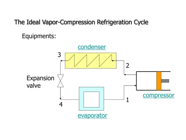
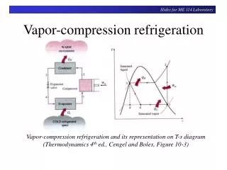
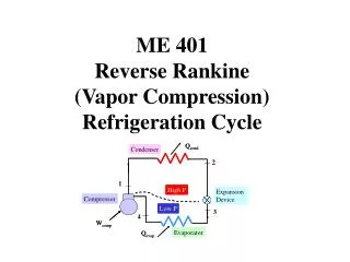
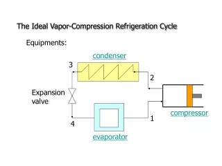
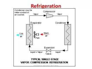
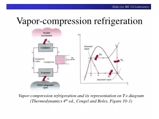
Vapor-compression refrigeration. Vapor-compression refrigeration and its representation on T-s diagram (Thermodynamics 4 th ed., Cengel and Boles, Figure 10-3). Question to Ponder.

E N D
Slides forME 114 Laboratory Vapor-compression refrigeration Vapor-compression refrigeration and its representation on T-s diagram (Thermodynamics 4th ed., Cengel and Boles, Figure 10-3)
Slides forME 114 Laboratory Question to Ponder You know that you have a saturated R12 mixture at the exit of the expansion valve. You have both a temperature and a pressure gauge at that point. If your pressure gauge reads 400 kPa when the actual pressure is 390 kPa (only a small error), what type of substance would it look like you have at this point – subcooled liquid, saturated mixture, or superheated vapor? Watch out for this problem whenever you have a mixture.
Slides forME 114 Laboratory Hilton Air Conditioning Unit • Steam is added at the inlet. • Air is preheated before sending it through the evaporator. If the temperature and relative humidity is right, liquid will condense as the air passes through the evaporator. • Air is then reheated near the end. • A normal air conditioning unit would not include all of these processes. • Air flow rate is measured at the exit of the unit with an orifice plate and manometer.
Slides forME 114 Laboratory Basic Equations • 1st law, no condensation or evaporation: Where is the only place in this system where the power input term would be kept? • 1st law with condensation: If we don’t measure the temperature of the condensate, what would be a good estimate of the temperature?
Slides forME 114 Laboratory Measuring Humidity: Approaches • Glass thermometer with wet wick will measure wet-bulb temperature, which can be used with dry-bulb temperature to determine humidity and state. (psychrometer) • Cellulose sponge-type material expands with changes in relative humidity, which can be calibrated or used with dial indicator. (hygrometer) • Electronic: Capacitance or resistance changes with relative humidity can be calibrated. Digital read-out common. (electronic hygrometer)
Slides forME 114 Laboratory Humidity Meters DMM/thermometer/ relative humidity meters (source: www.omega.com) Sling psychrometer (becoming obsolete) Source: sciencekit.com
Slides forME 114 Laboratory Measuring Mass Flow Rate With Pressure Drop • Orifice plates, flow nozzles, and venturi tubes are common. • The greater the air flow rate, the greater the pressure drop. • What general equation is used to calculate velocity? Flow nozzle Source: White, F.M., Fluid Mechanics 2nd Ed.
Slides forME 114 Laboratory Examples Orifice plate Venturi Rotameter (used for R12 measurement in this experiment) Manufacturer: Airflow Measurement Systems Source: http://lambdasquare.com/