Download
1 / 55
910 likes | 2.25k Views
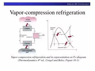
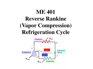
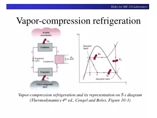
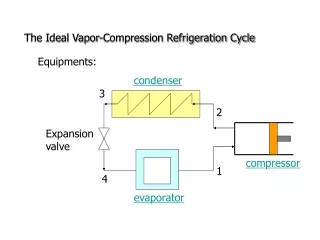
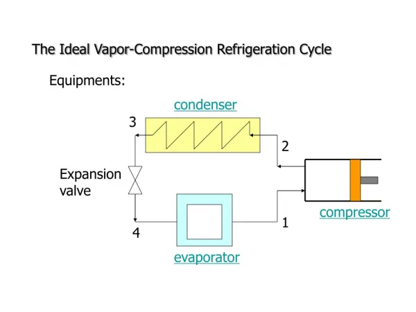
condenser. 3. 2. Expansion valve. compressor. 1. 4. evaporator. The Ideal Vapor-Compression Refrigeration Cycle. Equipments:. T. condenser. 2. 3. 3. 2. T H. Expansion valve. T L. 1. 4. compressor. 1. 4. s. evaporator. evaporator. compressor. condenser. Capillary tube.

E N D
condenser 3 2 Expansion valve compressor 1 4 evaporator The Ideal Vapor-Compression Refrigeration Cycle Equipments:
T condenser 2 3 3 2 TH Expansion valve TL 1 4 compressor 1 4 s evaporator
evaporator compressor condenser Capillary tube
h 2 1 3 4 s
p 3 2 4 1 h
10-2 Refrigerant High enthalpy of vaporization Not too low evaporator pressure Not too high condenser pressure Nontoxic Noncorrosive Chemically stable Low cost Good refrigerant • Ammonia • CFC(chlorofluorocarbons) • water
T 2 3 TH 1 4 T0 s
condenser evaporator Cascade Refrigeration Systems
T s T-s Diagram T0
T 5 4 condenser 4 3 6 2 5 heat exchanger Flash chamber 6 9 7 3 7 2 9 8 1 1 8 evaporator s 10-4-3 Multistage Compression Refrigeration Systems
T 3 condenser 2 4 2 3 refrigerator Alternative path 4 1 5 5 1 6 s Freezer 10-4-4 Multipurpose Refrigeration Systems with a Single Compressor
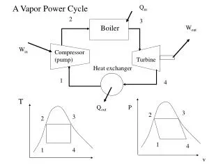
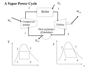
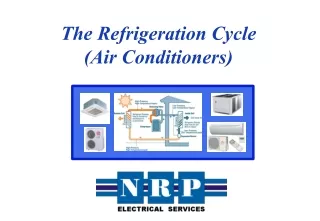
The vapor compression refrigeration cycle is a common method for transferring heat from a low temperature to a high temperature. The above figure shows the objectives of refrigerators and heat pumps. The purpose of a refrigerator is the removal of heat, called the cooling load, from a low-temperature medium. The purpose of a heat pump is the transfer of heat to a high-temperature medium, called the heating load. When we are interested in the heat energy removed from a low-temperature space, the device is called a refrigerator. When we are interested in the heat energy supplied to the high-temperature space, the device is called a heat pump. In general, the term heat pump is used to describe the cycle as heat energy is removed from the low-temperature space and rejected to the high-temperature space.
The performance of refrigerators and heat pumps is expressed in terms of coefficient of performance (COP), defined as Both COPR and COPHP can be larger than 1. Under the same operating conditions, the COPs are related by Can you show this to be true? Refrigerators, air conditioners, and heat pumps are rated with a SEER number or seasonal adjusted energy efficiency ratio. The SEER is defined as the Btu/hr of heat transferred per watt of work energy input. The Btu is the British thermal unit and is equivalent to 778 ft-lbf of work (1 W = 3.4122 Btu/hr). An EER of 10 yields a COP of 2.9. Refrigeration systems are also rated in terms of tons of refrigeration. One ton of refrigeration is equivalent to 12,000 Btu/hr or 211 kJ/min. How did the term “ton of cooling” originate?
The Vapor-Compression Refrigeration Cycle The vapor-compression refrigeration cycle has four components: evaporator, compressor, condenser, and expansion (or throttle) valve. The most widely used refrigeration cycle is the vapor-compression refrigeration cycle. In an ideal vapor-compression refrigeration cycle, the refrigerant enters the compressor as a saturated vapor and is cooled to the saturated liquid state in the condenser. It is then throttled to the evaporator pressure and vaporizes as it absorbs heat from the refrigerated space. The ideal vapor-compression cycle consists of four processes. Ideal Vapor-Compression Refrigeration Cycle Process Description 1-2 Isentropic compression 2-3 Constant pressure heat rejection in the condenser 3-4 Throttling in an expansion valve 4-1 Constant pressure heat addition in the evaporator
Example 11-1 Refrigerant-134a is the working fluid in an ideal compression refrigeration cycle. The refrigerant leaves the evaporator at -20oC and has a condenser pressure of 0.9 MPa. The mass flow rate is 3 kg/min. Find COPR and COPR, Carnot for the same Tmax and Tmin , and the tons of refrigeration. Using the Refrigerant-134a Tables, we have
The tons of refrigeration, often called the cooling load or refrigeration effect, are
Another measure of the effectiveness of the refrigeration cycle is how much input power to the compressor, in horsepower, is required for each ton of cooling. The unit conversion is 4.715 hp per ton of cooling.
Other Refrigeration Cycles Cascade refrigeration systems Very low temperatures can be achieved by operating two or more vapor-compression systems in series, called cascading. The COP of a refrigeration system also increases as a result of cascading.
Multipurpose refrigeration systems A refrigerator with a single compressor can provide refrigeration at several temperatures by throttling the refrigerant in stages.
Thermoelectric Refrigeration Systems A refrigeration effect can also be achieved without using any moving parts by simply passing a small current through a closed circuit made up of two dissimilar materials. This effect is called the Peltier effect, and a refrigerator that works on this principle is called a thermoelectric refrigerator.
Features of Actual Vapor-Compression Cycle Trefrigerant↑ Trefrigerant↓ through the condenser is increased relative to the temperature of the warm region, TH. The COP decreases – primarily due to increasing compressor work input – as the • temperature of the refrigerant passing through the evaporator is reduced relative to the temperature of the cold region, TC. • temperature of the refrigerant passing
Features of Actual Vapor-Compression Cycle Irreversibilities during the compression process are suggested by dashed line from state 1 to state 2. • An increase in specific entropy accompanies an adiabatic irreversible compression process. The work input for compression process 1-2 is greater than for the counterpart isentropic compression process 1-2s. • Since process 4-1, and thus the refrigeration capacity, is the same for cycles 1-2-3-4-1 and 1-2s-3-4-1, cycle 1-2-3-4-1 has the lower COP.
work required in an isentropic compression from compressor inlet state to the exit pressure work required in an actual compression from compressor inlet state to exit pressure Isentropic Compressor Efficiency The isentropic compressor efficiency is the ratio of the minimum theoretical work input to the actual work input, each per unit of mass flowing: (Eq. 6.48)
Actual Vapor-Compression Cycle State h(kJ/kg) 2s 272.39 2 280.15 3 91.49 4 91.49 1 241.35 Example: The table provides steady-state operating data for a vapor-compression refrigeration cycle using R-134a as the working fluid. For a refrigerant mass flow rate of 0.08 kg/s, determine the (a)compressor power, in kW, (b)refrigeration capacity, in tons, (c)coefficient of performance, (d)isentropic compressor efficiency.
Actual Vapor-Compression Cycle State h(kJ/kg) 2s 272.39 2 280.15 3 91.49 4 91.49 1 241.35 (a) The compressor power is 3.1 kW (b) The refrigeration capacity is 3.41 tons
Actual Vapor-Compression Cycle State h(kJ/kg) 2s 272.39 2 280.15 3 91.49 4 91.49 1 241.35 (c) The coefficient of performance is 3.86
Actual Vapor-Compression Cycle State h(kJ/kg) 2s 272.39 2 280.15 3 91.49 4 91.49 1 241.35 (d) The isentropic compressor efficiency is 0.8 = 80%
p-hDiagram • The pressure-enthalpy (p-h) diagram is a thermodynamic property diagram commonly used in the refrigeration field.
Selecting Refrigerants • Refrigerant selection is based on several factors: • Performance: provides adequate cooling capacity cost-effectively. • Safety: avoids hazards (i.e., toxicity). • Environmental impact: minimizes harm to stratospheric ozone layer and reduces negative impact to global climate change.
Refrigerant Types and Characteristics Global Warming Potential (GWP) is a simplified index that estimates the potential future influence on global warming associated with different gases when released to the atmosphere.
Refrigerant Types and Characteristics • Chlorofluorocarbons (CFCs) and Hydrochlorofluorocarbons (HCFCs)are early synthetic refrigerants each containing chlorine. Because of the adverse effect of chlorine on Earth’s stratospheric ozone layer, use of these refrigerants is regulated by international agreement. • Hydrofluorocarbons (HFCs) and HFC blendsare chlorine-free refrigerants. Blends combine two or more HFCs. While these chlorine-free refrigerants do not contribute to ozone depletion, with the exception of R-1234yf, they have high GWP levels. • Natural refrigerantsare nonsynthetic, naturally occurring substances which serve as refrigerants. These include carbon dioxide, ammonia, and hydrocarbons. These refrigerants feature low GWP values; still, concerns have been raised over the toxicity of NH3 and the safety of the hydrocarbons.
Vapor-Compression Heat Pump Systems • The objective of the heat pump is to maintain the temperatureof a space or industrial process above the temperature of the surroundings. • Principal control volumes involve these components: • Evaporator • Compressor • Condenser • Expansion valve
The Vapor-Compression Heat Pump Cycle Performance parameters Coefficient of Performance (Eq. 10.10) Carnot Coefficient of Performance (Eq. 10.9) This equation represents the maximum theoretical coefficient of performance of any heat pump cycle operating between cold and hot regions at TCand TH, respectively.
Vapor-Compression Heat Pump System State h(kJ/kg) 2 272.0 3 93.4 1 244.1 The method of analysis for vapor-compression heat pumps closely parallels that for vapor-compression refrigeration systems. Example: A vapor-compression heat pump cycle with R-134a as the working fluid maintains a building at 20oC when the outside temperature is 5oC. The refrigerant mass flow rate is 0.086 kg/s. Additional steady state operating data are provided in the table. Determine the (a)compressor power, in kW, (b)heat transfer rate provided to the building, in kW, (c)coefficient of performance.
Vapor-Compression Heat Pump System State h(kJ/kg) 2 272.0 3 93.4 1 244.1 (a) The compressor power is 2.4 kW (b) The heat transfer rate provided to the building is 15.4 kW
Vapor-Compression Heat Pump System State h(kJ/kg) 2 272.0 3 93.4 1 244.1 (c) The coefficient of performance is 6.4 Comment: Applying Eq. 10.9, the maximum theoretical coefficient of performance of any heat pump cycle operating between cold and hot regions at TC and TH, respectively is 19.5