Download

1 / 56
570 likes | 827 Views
United Arab Emirates University College of Engineering Graduation Project II. Analysis and Design of Concrete Highway Bridge. Done By: Abeer Abdullah 970722811 Amal Al-Amiri 199903930 Ramla Kalantar 199904023 Advisor: Dr. Bilal El-Ariss First Semester 2004/2005. Objectives.

E N D
United Arab Emirates UniversityCollege of Engineering Graduation Project II Analysis and Design of Concrete Highway Bridge Done By: Abeer Abdullah 970722811 Amal Al-Amiri 199903930 Ramla Kalantar 199904023 Advisor:Dr. Bilal El-Ariss First Semester 2004/2005
Objectives The Objective of the project is to: Learn structural analysis and design of concrete highway bridges. Acquire the knowledge and experience of applying the needed codes, specifications and soft ware.
Project discretion Abu Dhabi Municipality commissioned proposals for an Overpass Bridge over Abu Dhabi/Dubai highway at Al-Bahia residential area. The bridge is 95 m long (311.7 ft). The analysis and design of this bridge was done for the superstructure elements.
Design methods There are two methods used in structural design: • In 1900s, the method used in design was called the working-stress design (WSD) method. In this method service loads were used. • Since 1963, the ultimate-strength design method was rapidly used. In this method the service dead and live loads are multiplied by some load factors. The method used in our project is the ultimate-strength design method.
Structural Safety • In Ultimate-strength design method there are two approaches by which the structural safety can be obtained: • Load Factors • Strength Reduction Factors
Structural Safety • Load Factors: • The service loads are multiplied by some load factors that are larger than one. • Strength Reduction Factors:The material strength are multiplied by a reduction factor less than one.
Structural Safety • Strength Reduction Factors:The Code provides Φ values for several situations: • Flexure…………………………………………. Φ=0.9 • Shear…………………..………………………. Φ=0.85 • Axial compression with Sprials……………… Φ=0.75 • Ties………………………………………...…… Φ= 0.7 • Bearing on concrete………………………. …..Φ=0.7 (AASHTO 8.16.1.2.2)
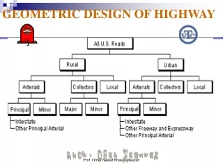
Design Specification AASHTO: AASHTO stands for American Association of State Highway and Transportation Officials. we used the following sections of AASHTO specifications: Section 3: Loads Section 8: Reinforced Concrete ACI Code: ACI stands for American Concrete Institute. ACI was founded in 1904
Material Used Reinforced Concreteis a composite material ofsteelbarsembedded in a hardenedconcrete.It is strong durable material that can formed into many varied shapes and sizes.
1. Concrete • Cement: OPC is the most common type in use. The main chemical compounds in cement are calcium silicate and aluminates. • Water: when water is added to cement to form cement past chemical reaction occur and the mix becomes stiffer with time (water cement ratio is an important factor affecting concrete strength)
Concrete • Aggregates : • The bulk of concrete is aggregate in the form of sand and gravel which bounded together by cement. • a. Coarse aggregate – gravel or crushed rock 5mm or larger in size. • b. Fine aggregate – Sand less than 5 mm in size. • Admixtures: • as setting accelerators or retarders, etc.
2. Steel Bars Reinforcing bars can be plan or deformed, the bar sizes used in U.S customary units ranges from #3 thought #18. While in SI units the bar are numbered 10, 13, 16, 22 and 43. these numbers represents the bar diameters approximately. In design we will use 420 MPa, the corresponding grade in U.S customary unit is 60,000 psi.
Concrete Steel Strength in tension Poor good Strength in compression good Good but slender bars will buckle Strength in shear Fair good Durability good Corrodes if unprotected Fire resistance good poor Comparing Properties
Advantages of reinforced concrete • Has a high compressive strength. • Resists fire actions. • Low maintenance material, has a very long service life. • An economical material and has an ability to be cast into a variety of shapes
Disadvantages of reinforced concrete • Has very low tensile strength. • Has a low strength per unit of weight of concrete which leads to heavy members. • The properties of concrete vary due to its proportioning and mixing.
Types of needed reinforcement 1.Reinforcement Requirements due to flexure The main reinforcing ,it may not be spaced farther on center than 3 times the slab thickness, or 18 in. One-fourth the positive moment reinforcement in continuous members shall extend along the same face of the members into the support in beams, at least 6 inches.
Types of needed reinforcement Development length (ld): The reinforcement bars must be extended some distance back into the support and out into the beam to anchor them or develop their strength. The basic development length shall be: No. 11 bars and smaller……… But not less than………………
Types of needed reinforcement 2.Parallel reinforcements In slabs, A percentage of the main positive moment reinforcement shall be distributed in the parallel direction of the traffic: Spacing limits for reinforcement: For cast-in-place concrete the clear distance between parallel bars in a layer shall not be less. 1.5 bar diameter, 1.5 times the maximum size of the coarse aggregate, 1.5 inches.
Types of needed reinforcement 3.Shrinkage Temperature Reinforcement: The total area of reinforcement provided shall be at least 1/8 square inch per foot in each direction. 4. Skin Reinforcement: skin reinforcement will be uniformly distributed along both side faces of the member for a distance d/2 nearest the flexural tension reinforcement. The area of skin reinforcement Ask per foot of height on each side face shall be. The maximum spacing of skin reinforcement shall not exceed d/6 and 12 inches.
Types of needed reinforcement 5.Shear Reinforcement If the diagonal tension exceeds the limited tensile strength of the concrete then shear reinforcement must be provided.
Stirrups perpendicular to the axis of the member. Welded wire fabric with wire located perpendicular to the axis of the member. Types of Shear Reinforcement
Types of Shear Reinforcement • Combinations of stirrups and bent longitudinal reinforcement. • Spirals.
Slab Design Slab is assumed to e a rectangular beam with a large ratio of width to depth. A 12-in wide piece of such a slab is designed as a rectangular beam.
c a b a b c Slab Design Slab sections
Slab Design Steps I ft strip of the slab will be designed and considers as a continues beam. • Live load Moment= (AASHTO 3.24.3.1) • Dead load Moment Mu= 1.4 MD +1.7ML
Slab Design Calculation h=10’’ , f’c=4000psi , fy=60,000psi • spans Section (b-b): • d =10’’-1’’-1/4’’ = 8.75’’ (in) • MD = 1.1 k.ft • ML = 4.94 k.ft • Mu = 1.4 MD +1.7ML = 9.938 k.ft • = 144.2psi • (Use table A.14) • ρ =0.0033 • As = ρbd = 0.3564 in2 • Use Bar #4 @ 6.5 in (As=0.36 in2)
Elevation view Cover: Top reinforcement…………….2 in. Bottom reinforcement…………1 in. Development length: For No. 4 bars = 1 ft For No. 5 bars = 1.25 ft
Girder Design Steps • Minimum depth for T-Girders (0.065S) (AASHTO table 8.9.2) • Compute Z larger of 0.9d or d-(hf/2) • Steel Area • Checking minimum reinforcement (larger of )
Girder Calculation • h = 6.93 ft = 83.16 in • d = 83.16-2-0.5-1.693/2 = 79.81 in = 6.65 ft • b = d/2 = 39.91 in • hf = 10 in
Interior Girder Reinforcement Skin reinforcement calculation:
Girder Shear Calculation Bar #3 is used for all shear reinforcement (stirrups) Girder Dimensions and Properties for Shear
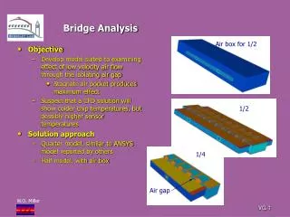
3’ 1.5’ Pier CapsDesign Pier Cap Bending Moment Diagram Due to Dead load
Reinforcement Calculation Bar #3 is used for all shear reinforcement (stirrups) Pier Cap Dimensions and Properties for Shear