Download
1 / 26
260 likes | 453 Views
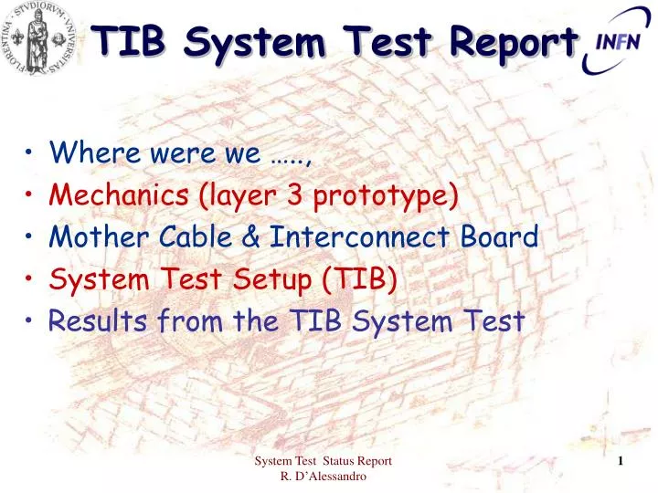
TIB System Test Report. Where were we ….., Mechanics (layer 3 prototype) Mother Cable & Interconnect Board System Test Setup (TIB) Results from the TIB System Test. TIB system test (July 2002). Not only for PS but “evolving” into a fully fledged mechanical and electrical test

E N D
TIB System Test Report • Where were we ….., • Mechanics (layer 3 prototype) • Mother Cable & Interconnect Board • System Test Setup (TIB) • Results from the TIB System Test System Test Status Report R. D’Alessandro
TIB system test (July 2002) • Not only for PS but “evolving” into a fully fledged mechanical and electrical test • NEEDS optical decoupling to achieve meaningful results • At first we needed a relatively good understanding of an optical system compared to a copper one: • Many measurements made, we gained full confidence. • Thanks to Roberto Cecchi for TIST. System Test Status Report R. D’Alessandro
La bara DOH CCU25 Power distribution PCB System Test Status Report R. D’Alessandro
Brico & Flexibility Short distance APV-AOH Final Kapton cable could be even shorter than this one Input/Output temporary connections on the back of module carrier System Test Status Report R. D’Alessandro
Mechanics Prepared by Pisa Layer 3 mock-up Up to 4 cooling loops (12 modules) Final dimensions System Test Status Report R. D’Alessandro
Mother Cable (1) System Test Status Report R. D’Alessandro
Mother cable (2) System Test Status Report R. D’Alessandro
Interconnect board Connects up to 4 MC Redundancy implemented Distributes also LV and HV Jumper disable of Hard Reset System Test Status Report R. D’Alessandro
What went on the mechanical structure • 3 modules: 180, 168, 177 (14 APV25) • 3 Analog OptoHybrids (3 fibres each) • 50 Ohms termination (100 Ohms in the future) • 1 CCU25 + DOH + Interconnect Board • Mother Cable with slight mods. • Power: Caen (counting room) prototype • 150 m cable LIC (100m Outer + 50m Inner) • 40 uF TOTAL LOAD CAPACITORS! • Battery for the control loop (5V for the DOH) System Test Status Report R. D’Alessandro
Cables System Test Status Report R. D’Alessandro
3Modules (complete MC) Fibre SPAGHETTI! CCU25 DLink AOH Cooling loops System Test Status Report R. D’Alessandro
Results • Bias = 200 V on 3 modules simultaneously • <1 microA total for the 3 modules • HV test with 1 module to 300V, on MC without modules to 450V • Able to read out pedestals and noise on all 3 modules at the same time • Calibration one module at a time System Test Status Report R. D’Alessandro
Pedestals ADC value peak ADC value deconv Strip no. Strip no. System Test Status Report R. D’Alessandro
Common mode noise 200V bias non-inv, peak Module 177 Module 180 ADC channels ADC channels System Test Status Report R. D’Alessandro
TIB System test in Florence Analog opto hybrid 50nF cap 22kW Bias line System Test Status Report R. D’Alessandro
New TIB hybrid layout (Dec. 2002 v11) Bias ring DCU input From J.D. Berst System Test Status Report R. D’Alessandro
TIB HV 300V on ARC Peak-Inverter on First and last strips~12ADC counts 2 noisy neighbours Unbonded strips System Test Status Report R. D’Alessandro
Same module but with 50nF capacitor to ground Edge effect reduced Furthermore only one strip is now affected …also the common mode is reduced System Test Status Report R. D’Alessandro
Same module on sys-test Module 177 with cap Peak mode Module 180 without cap System Test Status Report R. D’Alessandro
Signal shapes ADC value ADC value ns ns System Test Status Report R. D’Alessandro
Noise distribution (1) Peak mode Noise very low CMN is lower still S/N ratio Peak ~ 65 Ical=80! ADC channels System Test Status Report R. D’Alessandro
Noise distribution (2) Deconv mode S/N ratio Deconv ~ 52 Ical=80! ADC channels System Test Status Report R. D’Alessandro
LV behaviour Noise on 2.5V line 2.5V HARD RES (14 APVs + 9 Lasers) 10 mV/div 20 us/div DV=280 mV 200 mV/div 200 us/div System Test Status Report R. D’Alessandro
Conclusions • So far we have witnessed an excellent behaviour of the system. • Mother Cable is very well thought out, signals are clean, voltage drops negligeable. (Thanks to Giuseppe De Robertis) • The interconnect board has delivered at first go. (Thanks to Roberto Ciaranfi) • This Pisa-Florence common endeavour is getting along fine (incredible though this might seem) System Test Status Report R. D’Alessandro
Future • Need to go to 4 strings (12 modules) • MC are being loaded with components • Test redundancy (2nd DOH and CCU25s from CERN) • AOHs will be modified (100 Ohms) • We have started Xdaq migration. • This mock-up will be upgraded, while a new one is under construction ready for the next MC type. • New MC being designed (final version …) • DOM (DOH carrier) design underway System Test Status Report R. D’Alessandro
Interconnect Board (redundancy is implemented) System Test Status Report R. D’Alessandro