Download
1 / 16
180 likes | 373 Views
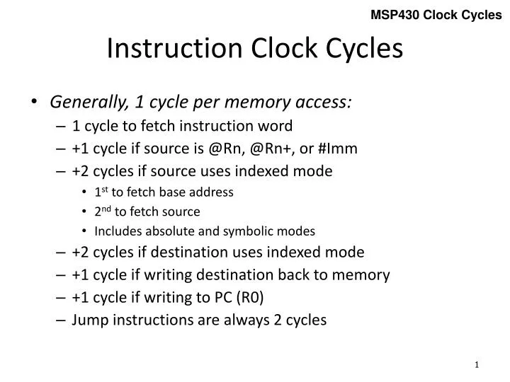
MSP430 Clock Cycles. Instruction Clock Cycles. Generally, 1 cycle per memory access: 1 cycle to fetch instruction word +1 cycle if source is @ Rn , @ Rn +, or # Imm +2 cycles if source uses indexed mode 1 st to fetch base address 2 nd to fetch source

E N D
MSP430 Clock Cycles Instruction Clock Cycles • Generally, 1 cycle per memory access: • 1 cycle to fetch instruction word • +1 cycle if source is @Rn, @Rn+, or #Imm • +2 cycles if source uses indexed mode • 1st to fetch base address • 2nd to fetch source • Includes absolute and symbolic modes • +2 cycles if destination uses indexed mode • +1 cycle if writing destination back to memory • +1 cycle if writing to PC (R0) • Jump instructions are always 2 cycles
add.w r5,r6 ;r6 <- r6 + r5 Address Bus Memory PC Address Bus 0x540a dst Registers temp ALU r5 PC r6 temp src 0x540a IR Data Bus
00 = Register Mode Addressing Modes add.w r4,r10 ;r10 = r4 + r10 Address Bus Memory CPU Registers Data Bus (1 cycle) IR 0x540a +2 PC PC 0x540a ADDER PC R4 R10 ALU (1 Cycle Instruction
01 = Indexed Mode Addressing Modes add.w 6(r4),r10 ;r10 = M(r4+6) + r10 Address Bus Memory CPU Registers Data Bus (1 cycle) IR 0x541a +2 +2 PC PC PC 0x541a ADDER PC 0x0006 Data Bus (+1 cycle) R4 Address Bus R10 Data Bus (+1 cycle) ALU (3 Cycle Instruction
10 = Indirect Register Mode Addressing Modes add.w @r4,r10 ;r10 = M(r4) + r10 Address Bus Memory CPU Registers Data Bus (1 cycle) IR 0x542a +2 PC PC 0x542a ADDER PC R4 Address Bus R10 Data Bus (+1 cycle) ALU (2 Cycle Instruction
Addressing Modes 11 = Indirect Auto-increment Mode add.w @r4+,r10 ;r10 = M(r4+) + r10 Address Bus Memory CPU Registers Data Bus (1 cycle) IR 0x543a +2 PC PC 0x543a ADDER PC 0002 Address Bus R4 R10 Data Bus (+1 cycle) ALU (2 Cycle Instruction
Addressing Modes 01 w/R0 = Symbolic Mode (PC Relative) add.w cnt,r10 ;r10 = M(cnt) + r10 Address Bus Memory CPU Registers Data Bus (1 cycle) IR 0x501a +2 +2 PC PC PC PC 0x501a ADDER PC 0x000c Data Bus (+1 cycle) Address Bus cnt R10 Data Bus (+1 cycle) ALU (3 Cycle Instruction
Addressing Modes 01 w/R2 = Absolute Mode add.w &cnt,r10 ;r10 = M(cnt) + r10 Address Bus Memory CPU Registers Data Bus (1 cycle) IR 0x521a +2 +2 PC PC PC 0x521a ADDER PC 0xc018 Data Bus (+1 cycle) 0000 Address Bus cnt R10 Data Bus (+1 cycle) ALU (3 Cycle Instruction
Addressing Modes 11 w/R0 = Immediate Mode add.w #100,r10 ;r10 = 100 + r10 Address Bus Memory CPU Registers Data Bus (1 cycle) IR 0x503a +2 +2 PC PC PC 0x503a ADDER PC 0x0064 Data Bus (+1 cycle) R10 ALU (2 Cycle Instruction
Addressing Modes Constant Generator add.w #1,r10 ;r10 = #1 + r10 Address Bus Memory CPU Registers Data Bus (1 cycle) IR 0x531a +2 PC PC 0x531a ADDER PC 0000 0001 0002 0004 0008 ffff R10 ALU (1 Cycle Instruction
Addressing Modes Three Word Instruction add.wcnt,var ;var = M(cnt) + M(var) Address Bus Memory CPU Registers Data Bus (1 cycle) IR 0x5090 +2 +2 +2 PC PC PC PC 0x5090 ADDER PC PC 0x000c Data Bus (+1 cycle) 0x0218 Data Bus (+1 cycle) Address Bus cnt Data Bus (+1 cycle) Address Bus var ALU Data Bus (+1 cycle) Data Bus (+1 cycle) (6 Cycle Instruction
Instruction Length 1 word (2 bytes) for instruction: Format I: Format II: Format III: Instruction Length • 1 additional word (2 bytes) for each of the following addressing modes: • Source index mode (As = 01) • mov10(r4),r5 • mov cnt,r5 • mov &P1IN,r5 • Source immediate mode (As = 11, S-reg = PC) (except constants -1, 0, 1, 2, 4, 8 which use S-reg = r2/r3) • mov #100,r5 • mov r4,10(r5) • mov r4,cnt • mov r4,&P1OUT • Destination index mode (Ad = 1)