Download
1 / 24
240 likes | 376 Views
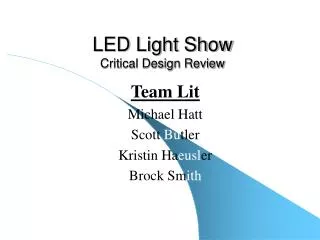
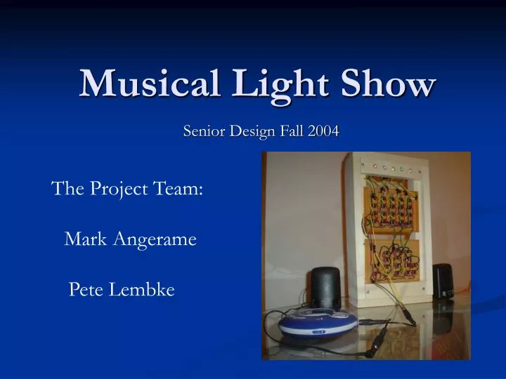
Musical Light Show. The Project Team:. Senior Design Fall 2004. Mark Angerame. Pete Lembke. Project Overview. To take an audio signal and transform it to a light show Filter audio signal into five unique frequency ranges to power individual LEDs

E N D
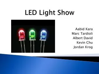
Musical Light Show The Project Team: Senior Design Fall 2004 Mark Angerame Pete Lembke
Project Overview • To take an audio signal and transform it to a light show • Filter audio signal into five unique frequency ranges to power individual LEDs • Amplify filtered signals to supply sufficient power to LEDs • To present the beat of the song in light form for all to enjoy
Why? • To present music in a unique way • Beat detection • To help those who are not musically inclined to determine the beat and to stay with it • Enhance the music listening experience at a low cost • To make music visually stimulating
Original Design The Original Block diagram: • Problems: • Three frequency ranges not enough
Original Design Original Filter Design: • Problems: • Output/Input resistance requirements not met • Passive filters not practical • Component values • Amount of loss
Original Design Original Power Amplifier Design: • Problems: • Output/Input resistance requirements not met • Not enough Gain • Unique Properties of light bulbs
Final Design • Solutions • We expanded our circuit to include five frequency ranges • 0-170 Hz, 170 Hz – 600 Hz, 600 Hz – 3000 Hz, 3000 Hz – 12000 Hz, >12000 Hz • Switched to Active Filters • Switched to large LEDs from light bulbs • Redesigned the power circuit to accommodate large LEDs
Active Filters Schematic of the 170-600 Hz Band pass filter:
Active Filters Simulations of Filters:
Power Amplifier Schematic of Power Amplifier Circuit:
Lighting • LEDs vs Lights • Original Design did not work • Two Options: • Use Large Light bulbs controlled by PIC, RMS, and Relay • Use High Power LEDs
Construction • The filters and amplifiers were soldered onto a board and mounted into a box Filters
Construction • The filters and amplifiers were soldered onto a board and mounted into a box Amplifiers
Testing • Actual output current using frequency sweep
Testing • Function generator as input • Filter output on oscilloscope • Amplifier output on oscilloscope • LEDs light up
Other Testing • Various styles of music • Rock, rap, alternative, pop, techno • Unique output patterns for different music styles and songs • Voice detection • Some instrument recognition • Bass beat extremely prominent
Successes and Challenges • The project worked • It has received rave reviews from those who have witnessed its awesomeness • Many people have expressed a desire to own one of their own • All of the work and effort resulted in a project that both works and we are proud of
Successes and Challenges • Where to begin designing our circuit • Hardware limitations • Having to redesign the circuits after discovering they don’t work • General organization and time constraints