Download
1 / 16
180 likes | 301 Views
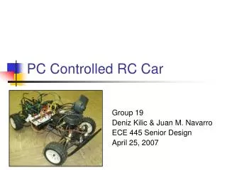
Thomas Chau, Ben Sack, Peter Tsonev. RC Car. Overview. Goal : to build a smart RC car that corrects itself using sensors. Objective : testing our run at high speed towards an object and halt before crashing. Architecture and Design. NIOS system. PWM component to interface Altera with Car

E N D
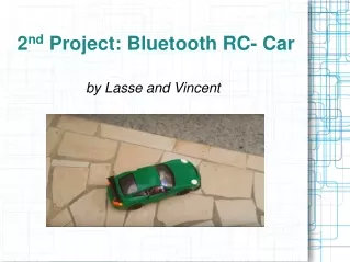
Overview • Goal: to build a smart RC car that corrects itself using sensors. • Objective: testing our run at high speed towards an object and halt before crashing.
Architecture and Design • NIOS system. • PWM component to interface Altera with Car • Ultrasonic Sensor component with interrupts. • Software component – feedback loop integrating sensor readings and outputting to PWM. • Additional servo to rotate sensor 90 degrees.
Algorithm • D = distance read from sensor (inches) • S = speed calculated from D and previous D (inches per second) • While (D is not target D) • Read D. Let S = (D' – D) * dt • Let new speed = function (D, S) • Let PWM level = normalization (speed) => [6% to 9%] • Write PWM level to register.
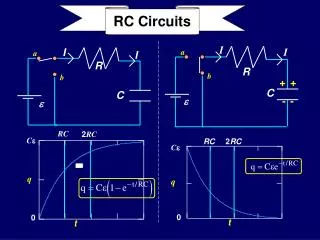
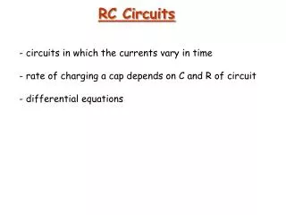
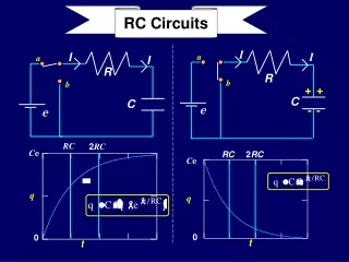
PID Equations • Two equations; two degrees of freedom • Gain equation tries to get car as close to target as possible. • Differentiatorequation opposes the first equation if the speed of approach is too high. • The balance of the two equations brings the car to target.
Implementation • Engineering a good feedback loop takes a great deal of experimentation. • Precise distance measurements are tough; precise speed measurements are even harder.
Implementation Cont'd • PID theory is for linear behavior; however, the physical system of the car and especially the throttle control is highly nonlinear. • Our task is critical damping. The PID equations work best for under-damping. • Solution: introduce a nonlinearity in the equations; the differentiator is also a measure of distance to target. (Smaller distance -> more reverse throttle)
Results • Engine lost reverse throttle capability. • The following graphs show our measurements while the engine was still performing. • Graphs: Overdamping, Critical Damping, Dirty Measurements
Results • Graph
New Demo instead of Throttle Demo • Uses PID concept except with steering rather than braking. • New challenges: sensor reads wall at a bad incident angle. • Nonlinear throttle affects turning rate. • Poor sensor resolution requires larger distances.
Difficulties • The car exploded • Physical difficulties: measurement; figuring out parameters for feedback equations; hacking the hardware; fundamental nonlinearities. • Physical limitations; ultrasonic sensor updating every 50ms with 1” granularity. Car engine with very rough speed control. Unpredictable battery conditions.
Lessons Learned • Be careful not to jerk the PWM levels, damaging transistors. • Wiring is too low-level; it complicates debugging and increases the development time. • Data filtering for dirty measurement data; unforeseen sources of interference (ethernet, battery, servos, engines, etc.)
Thanks! • Peter cuts a breadboard down to size.