Download
1 / 15

E N D
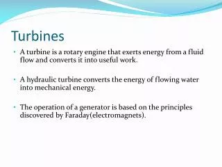
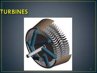
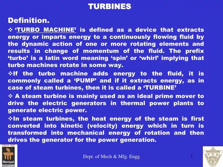
TURBINES Definition. ‘TURBO MACHINE’ is defined as a device that extracts energy or imparts energy to a continuously flowing fluid by the dynamic action of one or more rotating elements and results in change of momentum of the fluid. The prefix ‘turbo’ is a latin word meaning ‘spin’ or ‘whirl’ implying that turbo machines rotate in some way. If the turbo machine adds energy to the fluid, it is commonly called a ‘PUMP’ and if it extracts energy, as in case of steam turbines, then it is called a ‘TURBINE’ A steam turbine is mainly used as an ideal prime mover to drive the electric generators in thermal power plants to generate electric power. In steam turbines, the heat energy of the steam is first converted into kinetic (velocity) energy which in turn is transformed into mechanical energy of rotation and then drives the generator for the power generation. Dept. of Mech & Mfg. Engg
The propelling force in a steam turbine depends mainly on the dynamic action of the steam. The steam is made to fall in its pressure by expanding in a nozzle.Due to this fall in pressure; a certain amount of heat energy is converted into kinetic energy which sets the steam to flow with a greater velocity. The rapidly moving particles of the steam enter the rotating part of the turbine where it undergoes a change in the direction of motion which gives rise to a change of momentum and therefore a force. This constitutes the driving force of the turbine. Principle of working. Dept. of Mech & Mfg. Engg
PRINCIPLE Dept. of Mech & Mfg. Engg
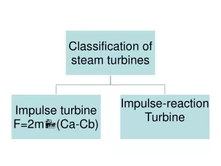
Classification of Steam Turbines. Based on the kind of energy transfer, steam turbines are classified as, a) Impulse Turbines b) Reaction Turbines Impulse Turbines: In impulse turbines, energy transfer across the rotating element takes place due to the dynamic pressure change only and static pressure remains the same. In this type of turbine, the steam is initially expanded in a nozzle from high pressure to low pressure. The high velocity jet of steam coming out of the nozzle is made to glide over a curved vane, called ‘blade’. Dept. of Mech & Mfg. Engg
Q VH NOZZLE PH HIGH PRESSURE STEAM EXHAUST STEAM R Velocity Variation Pressure Variation VL C PL B TURBINE SHAFT MOVING BLADES Rotor Blades Fig.3.10 Schematic of Impulse Turbine Nozzle Fig.3.11 Diagrammatic Impulse Turbine Pressure-velocity changes over Impulse steam Turbine. • The jet of steam gliding over the blade gets deflected very nearly in the circumferential direction. This causes the particles of steam to suffer a change in the direction of motion which gives rise to a change of momentum and therefore a force, which will be centrifugal in nature. Dept. of Mech & Mfg. Engg
The resultant of all these centrifugal forces acting on the entire curved surface of the blade causes it to move. • They will be moved by the action of the steam, and they in turn set the rotor in continuous rotation. The rotation of the rotor makes all the blades fitted on the rim to get exposed to the action of the steam jet in succession. • In the impulse turbines the steam is expanded from its high initial pressure to a lower pressure before it is delivered to the moving blades on the rotor. The pressure of the steam over the blades will be at a lower pressure • However, the velocity of the steam continuously decreases as it glides over the blades owing to the conversion of kinetic energy into mechanical energy of rotation. Thus in the impulse turbines the mechanical power is produced by the combined action of the resultant of the centrifugal pressures due the change of momentum and the effect of change of velocity of the steam as it glides over the blades Dept. of Mech & Mfg. Engg
Since the expansion of the steam takes place in the nozzle, the pressure drop is represented by the curve AB. As there will be no change in the pressure of the steam that is passing over the blade, this flow is represented by the horizontal line BC. Since the velocity of the steam in the nozzle increases due to the expansion of the steam, the increase in the velocity of the steam is represented by the curve PQ. • As the blades absorb the kinetic energy of the steam as it flows over it, the velocity decreases. This is represented by the curve QR. Dept. of Mech & Mfg. Engg
Fig. 3.12: Principle of working –Reaction steam Turbine • In Reaction turbines, energy transfer takes place across the rotating element due to both static pressure energy change and dynamic pressure energy change. • In this type of turbine the high pressure steam does not initially expand in the nozzle as in the case of impulse turbine, but instead directly passes onto the moving blades. Dept. of Mech & Mfg. Engg
Blades shapes of reaction turbines are designed in such a way that the steam flowing between the blades will be subjected to the nozzle effect. Hence the pressure of the steam drops continuously as it flows over the blades causing, simultaneous increase in the velocity of the steam. Thus the reaction force acting on the blades constitutes a fraction of the propelling force driving the turbine rotor. In addition to this reaction force, there is also the centrifugal force exerted by the steam due to the change in the momentum. This reduces the velocity of the steam. Thus the net force acting on the moving blades of a reaction turbine isthe vector sum of the centrifugal and the reaction forces. Therefore the expansion of the steam takes place both in the fixed and the moving blades. The fixed blade rings between the two moving blade rotors enables to deflect and guide the steam to enter from one row of moving blades to the next row. Dept. of Mech & Mfg. Engg
Forces acting on a reaction blade. • Reaction force: This force is due to the change in change in momentum and relative velocity of the steam while passing over the blade passage. • Centrifugal force: This is a centrifugal force acting on the blade due to change in radius of steam entering and leaving the turbine. • Resultant force: This is the resultant of Reaction force and Centrifugal force. Dept. of Mech & Mfg. Engg
Pressure-Velocity change over reaction turbine • The high pressure steam passing in the first row of fixed blades undergoes a small drop in pressure causing the increase in the velocity of the steam. It then enters the first row of moving blades where it suffers further drop in pressure and the velocity energy is converted into the mechanical energy of rotation of the rotor Dept. of Mech & Mfg. Engg
Unlike the impulse turbine; no nozzles as such are mounted in a reaction turbine. The fixed blades act as nozzles in which the velocity of the steam is increased and they also direct the steam towards the moving blades at the correct angle. • The steam also expands in the moving blades of a reaction turbine with consequent pressure drop and velocity increase in these moving blades. • There is an enthalpy drop in the steam during its passage through the blades which produces acceleration. • The extent to which the enthalpy drop occurs in the moving blades is called the ‘Degree of Reaction’. Dept. of Mech & Mfg. Engg
IMPULSE V/S REACTION TURBINE Dept. of Mech & Mfg. Engg
1.Steam completely expands from a high pressure to low pressure in the nozzle expands before it enters the moving blades. 2. The symmetrical profile of the moving blades provides a uniform section for the flow of steam; causing no expansion of the steam. 3. The pressure of the steam at both the ends of the moving blades and as well as while passing over them remains constant. The high pressure steam continuously expands successively in both the fixed and moving blades. The asymmetrical profile of both the moving and fixed blades provides a varying section for the flow of steam between them which causes the expansion of the steam. The pressure of the steam at both the ends of the fixed and moving blades and as well as while passing over them are different. Differences between Impulse and Reaction turbines. Dept. of Mech & Mfg. Engg
4.Because of the large drop in pressure in the nozzle, and as well as the rotor; speeds are high. 5. Because of the larger pressure drop in the nozzle and less number of stages, size of the impulse turbine for the same power output is comparatively small. 6. Occupies less space per unit power. 7. Suitable for small power generation prime movers. 8. Due to high rotor speeds compounding is required to reduce the speed. Due to the smaller pressure drop over both fixed and moving blades, both the steam speed and the rotor speed are relatively low. Because of the smaller pressure drop in every stage, and more number of stages, size of the reaction turbine for the same power output is large. Occupies more space per unit power. Suitable for medium and high power generation prime movers. The speeds are relatively less and hence no compounding is required. Dept. of Mech & Mfg. Engg