Download

1 / 21
230 likes | 506 Views
Instruction Execution in Simple Computer Instruction fetch Instruction decode Oprand fetch Execute PC update. MicroMIPS: Hardware realizations of 22-instruction version MiniMIPS. 13.1 A Small Set of Instruction. Table 13.1 The MicroMIPS instruction set.*.

E N D
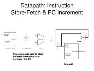
Instruction Execution in Simple Computer • Instruction fetch • Instruction decode • Oprand fetch • Execute • PC update
MicroMIPS: Hardware realizations of 22-instruction version MiniMIPS. 13.1 A Small Set of Instruction
Figure 13.1 MicroMIPS instruction formats and naming of the various fields.
Read out the contents of source register rs and rt, and forward them as inputs to ALU. Tell ALU what operation to perform. Write the output of ALU in destination register rd. Execution sequence of 7 R-format instructions (add, sub, slt, and, or, xor, nor)
Read out the contents of source register rs. Add the number read out from rs to the immediate value in the instruction to form a memory address. Read from or write into memory as the specified address. In the case of lw, place the word read out from memory into rs. Execution sequence of 6 I-format instructions (lui, addi, slti, andi, ori, andi, ori, xori)
Compare the contents rs and rt. If condition holds, the immediate field is added to (PC)+4 and result is written back into PC; otherwise (PC)+4 is written back into PC. Branch instruction (beq, bne) Branch instruction (bltz) Branch decision is based on sign bit of content rs rather than comparison of two register contents.
PC is unconditionally modified to allow the next instruction to be fetched from the target address. Jump target address comes from the instruction itself. Jump instruction (j, jal) System call (syscall) Jump target address is a known constant associated with the location of an operating system routine.
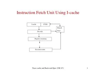
13.2 Instruction Execution Unit Figure 13.2 Abstract view of the instruction execution unit for MicroMIPS.For naming of instruction fields, see Figure 13.1.
13.3 A Single-Cycle Data Path $31 RegDst 00: rt, 01: rd, 10: $31 (jal) ALUSrc 0: rt, 1:imm. oprand, sign extension RegInSrc 00: data cache, 01:ALU, 10: Inc. PC
(j inst) (jr inst) Figure 13.4 Next-address logic for MicroMIPS (see the top part of Figure 13.3).
13.5 Deriving the Control Signals 17 control signals for 22 MicroMIPS instructions. Table 13.2 Control signals for the single-cycle MicroMIPS implementation.
17 Boolean functions for 12 inputs (6 bits for op, 6 bits for fn) Table 13.3 Control signal settings for the single-cycle MicroMIPS instruction execution unit.*
Drawback of above method If we later decide to modify the instruction set of the machine or add new instructions to it, the entire design must be changed.
Two-step approach to the synthesis of control circuits Figure 13.5 Instruction decoder for MicroMIPS built of two 6-to-64 decoders.
Consider some of the control signals have a large number of entries in their truth table, thus requiring multi-level ORing. Here, we introduce auxiliary signals. Auxiliary signals: arithInst = addInst subInst sltInst addiInst sltiInst logicInst = andInst orInst xorInst norInst andiInst oriInst xori immInst = luiInst addiInst sltiInst andiInst oriInst xoriInst Then, for example, RegWrite = luiInst arithInst logicInst lwInst jal
13.6 Performance of Single-Cycle Design In above implementation, each instruction is executed in one machine cycle. That is, CPI =1.The performance is determined by the slowest instruction, lw. This corresponds to 125MHz, and a performance of 125MIPS.
Signal propagation path in MicroMIPS Figure 13.6 The MicroMIPS data path unfolded (by depicting the register write step as a separate block) to allow better visualization of the critical-path latencies for various instruction classes.
MicroMIPS with mixed instruction set. The average performance is 157MIPS.