Download
1 / 33
440 likes | 649 Views
The Future of RF Microelectromechanical Systems (MEMS). Clark T.-C. Nguyen Dept. of Electrical Engineering & Computer Sciences University of California Berkeley, California 94720 E-mail : ctnguyen@eecs.berkeley.edu BEARS’07 Feb.15, 2007. Outline.

E N D
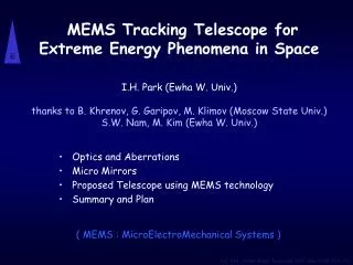
The Future of RF Microelectromechanical Systems (MEMS) Clark T.-C. Nguyen Dept. of Electrical Engineering & Computer Sciences University of California Berkeley, California 94720 E-mail: ctnguyen@eecs.berkeley.edu BEARS’07 Feb.15, 2007
Outline • Motivation: Miniaturization of Transceivers • need for high-Q • Micromechanical Resonators • clamped-clamped beams • micromechanical disks • Micromechanical Circuits • micromechanical filters • arraying techniques • Towards RF Channel-Selection • Conclusions
RF Power Amplifier Diplexer 925-960MHz RF SAW Filter 897.517.5MHz RF SAW Filter 1805-1880MHz RF SAW Filter Dual-Band Zero-IF Transistor Chip 26-MHz Xstal Oscillator 3420-3840MHz VCO Antenna Mixer I LPF I A/D Diplexer AGC 0o Xstal Osc 90o RF PLL RXRF LO RF BPF Q LNA A/D From TX AGC Mixer Q LPF Motivation: Miniaturization of RF Front-Ends Problem: high-Q passives pose a bottleneck against miniaturization Wireless Phone
0o 0o 90o 90o Multi-Band Wireless Handsets I Duplexer • The number of off-chip high-Q passives increases dramatically • Need: on-chip high-Q passives CDMA LNA RF BPF LPF From TX A/D I RF BPF AGC Antenna GSM 900 LNA LPF Q RF BPF A/D PCS 1900 Q I AGC LNA RXRF LO RF BPF DCS 1800 ÷ (N+1)/N Xstal Osc RXRF Channel Select PLL LNA RF BPF Duplexer Tank Q CDMA-2000 LNA From TX RF BPF Duplexer LNA WCDMA From TX
Vibrating Resonator 1.5-GHz, Q~12,000 Vibrating Resonator 62-MHz, Q~161,000 All High-Q Passives on a Single Chip 0.25 mm CDMA RF Filters (869-894 MHz) Optional RF Oscillator Ultra-High Q Tanks GSM 900 RF Filter (935-960 MHz) 0.5 mm PCS 1900 RF Filter (1930-1990 MHz) Low Freq. Reference Oscillator Ultra-High Q Tank DCS 1800 RF Filter (1805-1880 MHz) CDMA-2000 RF Filters (1850-1990 MHz) WCDMA RF Filters (2110-2170 MHz)
Agilent FBAR Thin-Film Bulk Acoustic Resonator (FBAR) • Piezoelectric membrane sandwiched by metal electrodes • extensional mode vibration: 1.8 to 7 GHz, Q ~500-1,500 • dimensions on the order of 200mm for 1.6 GHz • link individual FBAR’s together in ladders to make filters h freq ~ thickness • Limitations: • Q ~ 500-1,500, TCf ~ 18-35 ppm/oC • difficult to achieve several different freqs. on a single-chip
mMechanical Resonator Low Q Vib. Amplitude High Q 110 Hz Freq. [Bannon et al JSSC’00] Performance: Lr=40.8mm mr ~ 10-13 kg Wr=8mm, hr=2mm d=1000Å, VP=5V Press.=70mTorr Vibrating “A” String (110 Hz) fo=8.5MHz Qvac=8,000 Qair~50 Stiffness Freq. Equation: Freq. Mass Basic Concept: Scaling Guitar Strings Guitar String Guitar
Surface Micromachining • Fabrication steps compatible with planar IC processing
Oscilloscope Output Waveform Single-Chip MEMS-Transistor Integration • Completely monolithic, low phase noise, high-Q oscillator (effectively, an integrated crystal oscillator) [Nguyen, Howe JSSC’99] [Nguyen, Howe 1993] • To allow the use of >600oC processing temperatures, tungsten (instead of aluminum) is used for metallization
mMechanical Resonator Low Q Vib. Amplitude High Q 110 Hz Freq. [Bannon et al JSSC’00] Performance: Lr=40.8mm mr ~ 10-13 kg Wr=8mm, hr=2mm d=1000Å, VP=5V Press.=70mTorr Vibrating “A” String (110 Hz) fo=8.5MHz Qvac=8,000 Qair~50 Stiffness Freq. Equation: Freq. Mass Basic Concept: Scaling Guitar Strings Guitar String Guitar
Q ~10,000 wo w Note: If VP = 0V device off C(t) Stiffness Young’s Modulus VP Density Mass Radial-Contour Mode Disk Resonator Input Electrode Supporting Stem Output Electrode Disk R io vi VP Frequency: Smaller mass higher freq. range and lower series Rx (e.g., mr = 10-13 kg)
1.51-GHz, Q=11,555 Nanocrystalline Diamond Disk mMechanical Resonator • Impedance-mismatched stem for reduced anchor dissipation • Operated in the 2nd radial-contour mode • Q ~11,555 (vacuum); Q ~10,100 (air) • Below: 20 mm diameter disk Design/Performance: R=10mm, t=2.2mm, d=800Å, VP=7V fo=1.51 GHz (2nd mode), Q=11,555 Polysilicon Stem (Impedance Mismatched to Diamond Disk) fo = 1.51 GHz Q = 11,555 (vac) Q = 10,100 (air) Polysilicon Electrode Q = 10,100 (air) R Mixed Amplitude [dB] CVD Diamond mMechanical Disk Resonator Ground Plane Frequency [MHz] [Wang, Butler, Nguyen MEMS’04]
Commercialization of MEMS Timekeepers ‘s pure silicon high-Q vibrating mmechanical resonator oscillator mMechanical Resonator Die ASIC Discera TCMO Package Cap • Smaller size • Lower cost • Lower power consumption High-Q, low drift, make possible a very stable, low power timekeeper $3.5 Billion Market
GSM-Compliant Oscillator 9-Wine-Glass Disk Array Q = 118,900 ,Rx = 2.56 kW Custom IC fabricated via TSMC 0.35mm process Output Single WG Disk @ 62 MHz Phase Noise [dBc/Hz] 9-WG Disk Array @ 62 MHz Input GSM spec [Y.-W. Lin, Nguyen, IEDM’05] Satisfies Global System for Mobile Communications (GSM) phase noise specifications! Down to 13 MHz All made possible by mechanical circuit design! Offset Frequency [Hz]
RQ xo xo vo vo vi vi vi vi vo vi RQ VP Loss Pole w w w w wo wo wo wo Micromechanical Filter Design Basics Termination Resistor Coupling Beam Bridging Beam Disk Resonator
VP In Out Sharper roll-off Loss Pole 3CC 3l/4 Bridged mMechanical Filter Performance: fo=9MHz, BW=20kHz, PBW=0.2% I.L.=2.79dB, Stop. Rej.=51dB20dB S.F.=1.95, 40dB S.F.=6.45 Transmission [dB] Pin=-20dBm Design: Lr=40m Wr=6.5m hr=2mLc=3.5mLb=1.6m VP=10.47VP=-5dBmRQi=RQo=12k [S.-S. Li, Nguyen, FCS’05] Frequency [MHz] [Li, et al., UFFCS’04]
vo vi Micromechanical Filter Circuit Bridging Beam RQ Input 3l/4 Coupling Beam l/4 Resonator vi Output l/4 vo VP RQ w 1:hc hc:1 1:hc hc:1 1/kr 1/kr 1/kr -1/ks -1/ks mr cr mr cr -1/ks -1/ks mr cr he:1 1:he 1/ks Co 1/ks Co 1:hb hb:1 1/kb 1/kb -1/kb
vo vi Micromechanical Filter Circuit Bridging Beam RQ Input 3l/4 Coupling Beam l/4 Resonator vi Output l/4 vo VP RQ w 1:hc hc:1 1:hc hc:1 1/kr 1/kr 1/kr -1/ks -1/ks mr cr mr cr -1/ks -1/ks mr cr he:1 1:he 1/ks Co 1/ks Co 1:hb hb:1 1/kb 1/kb -1/kb
vo vi Micromechanical Filter Circuit Bridging Beam RQ Input 3l/4 Coupling Beam l/4 Resonator vi Output l/4 vo VP RQ w 1:hc hc:1 1:hc hc:1 1/kr 1/kr 1/kr -1/ks -1/ks mr cr mr cr -1/ks -1/ks mr cr he:1 1:he 1/ks Co 1/ks Co 1:hb hb:1 1/kb 1/kb -1/kb
vo vi w Micromechanical Filter Circuit Bridging Beam RQ Input 3l/4 Coupling Beam l/4 Resonator vi Output All circuit element values determined by CAD layout l/4 vo VP RQ Amenable to automated circuit generation 1:hc hc:1 1:hc hc:1 1/kr 1/kr 1/kr -1/ks -1/ks mr cr mr cr -1/ks -1/ks mr cr he:1 1:he 1/ks Co 1/ks Co 1:hb hb:1 1/kb 1/kb -1/kb
VP In Out Sharper roll-off Loss Pole 3CC 3l/4 Bridged mMechanical Filter Performance: fo=9MHz, BW=20kHz, PBW=0.2% I.L.=2.79dB, Stop. Rej.=51dB20dB S.F.=1.95, 40dB S.F.=6.45 Transmission [dB] Pin=-20dBm Design: Lr=40m Wr=6.5m hr=2mLc=3.5mLb=1.6m VP=10.47VP=-5dBmRQi=RQo=12k [S.-S. Li, Nguyen, FCS’05] Frequency [MHz] [Li, et al., UFFCS’04]
Ws Lr gap, do h 50W-Terminated 68-MHz Coupled-Array mMechanical Filter fo=68MHz BW=190kHz PBW=0.28% I.L.<2.7dB Use square-plate mmechanical resonator arrays Lower end resonator impedance & raise power handling 50W termination w/ L-network RQ = 12kW Rterm = 50W Square-Plate Micromechanical Resonator Lr= 16mm h = 2.2mm do = 90nm Coupling Beam [Demirci, Nguyen 2005]
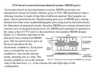
The higher the Q of the Pre-Select Filter the simpler the demodulation electronics Desired Signal Received Power Pre-Select Filter in the GHz Range wRF Frequency Demodulation Electronics Motivation: Need for High Q Presently use resonators with Q’s ~ 400 Antenna Wireless Phone
The higher the Q of the Pre-Select Filter the simpler the demodulation electronics Pre-Select Filter in the GHz Range Demodulation Electronics Motivation: Need for High Q Presently use resonators with Q’s ~ 400 Desired Signal Received Power wRF Frequency Antenna Wireless Phone
The higher the Q of the Pre-Select Filter the simpler the demodulation electronics Pre-Select Filter in the GHz Range Demodulation Electronics Motivation: Need for Q’s > 10,000 Presently use resonators with Q’s ~ 400 If can have resonator Q’s > 10,000 Desired Signal Received Power wRF Frequency Antenna Wireless Phone
The higher the Q of the Pre-Select Filter the simpler the demodulation electronics Pre-Select Filter in the GHz Range Demodulation Electronics Motivation: Need for Q’s > 10,000 Presently use resonators with Q’s ~ 400 If can have resonator Q’s > 10,000 Desired Signal Received Power wRF Frequency Antenna Wireless Phone
The higher the Q of the Pre-Select Filter the simpler the demodulation electronics Pre-Select Filter in the GHz Range Demodulation Electronics Non-Coherent FSK Detector? (Simple, Low Frequency, Low Power) Front-End RF Channel Selection Substantial Savings in Cost and Battery Power Motivation: Need for Q’s > 10,000 Presently use resonators with Q’s ~ 400 If can have resonator Q’s > 10,000 Desired Signal Received Power wRF Frequency Antenna Wireless Phone
The higher the Q of the Pre-Select Filter the simpler the demodulation electronics Pre-Select Filter in the GHz Range Demodulation Electronics Direct-Sampling A/D Converter Software-Defined Radio Front-End RF Channel Selection Motivation: Need for Q’s > 10,000 Presently use resonators with Q’s ~ 400 If can have resonator Q’s > 10,000 Desired Signal Received Power wRF Frequency Antenna Wireless Phone Maximum Flexibility one circuit satisfies all comm. standards
RF Channel-Select Filter Bank Switch filters on/off via application and removal of dc-bias VP, controlled by a decoder Bank of UHF mmechanical filters Remove all interferers! RF Channels 1 2 3 4 5 6 7 n Transmission Transmission Transmission Freq. Freq. Freq.
Conclusions • Vibrating RF MEMS have achieved • Q’s >10,000 at GHz frequencies in sizes less than 20 mm in diameter and w/o the need for vacuum encapsulation • TCf’s < -0.24 ppm/oC (better than quartz) • aging at least on par with quartz • circuit-amenable characteristics • VLSI potential • Probable evolution of products based on vibrating RF MEMS: • timing devices using micromechanical resonators • communication-grade frequency synthesizers • single-chip of all needed high-Q passives • mechanical radio front-ends … • In Research: Time to turn our focus towards mechanical circuit design and mechanical integration • maximize, rather than minimize, use of high-Q components • e.g., RF channelizer paradigm-shift in wireless design • even deeper frequency computation • What’s possible with an unlimited supply of high-Q passives?