Download
1 / 23
230 likes | 385 Views
Behavioural visualization of model based systems. Michel Reniers QA & Test 2009 October 23, 2009. Personal background. Assistant professor at TU/e Background in formal methods for specification and verification of behaviour of systems (MSC, process algebras)

E N D
Behavioural visualization of model based systems Michel Reniers QA & Test 2009 October 23, 2009
Personal background QA & Test 2009: M.A.Reniers Assistant professor at TU/e Background in formal methods for specification and verification of behaviour of systems (MSC, process algebras) ITEA Twins project (2007-2009): Optimizing HW-SW Co-Design Flow for Software Intensive System Development Partners are: a.o. SQS and Innovalia
Motivation QA & Test 2009: M.A.Reniers Growing number of SW-HW embedded machines Shorter time to market, growing complexity, increasing product quality Problematicintegration/development trajectory PAGE 3
Motivation Validation Requirements Formal model Temporal logic formula System Verification QA & Test 2009: M.A.Reniers
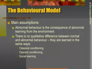
Introduction - Problems Current trends show that industrial systems are being development in a multi-disciplinary environment Different disciplines = different methods, techniques and tools Developing a multi-disciplinary system is a difficult trajectory Incompatible information resources Hard to exchange information between disciplines Difficult to predict system behaviour Concurrent behaviour Exceptional cases can easily be missed Forgotten behaviour QA & Test 2009: M.A.Reniers
Introduction – Range of Solutions Guard coherence and tune mono-disciplinary designs designs need to be kept native designs must be exchanged between disciplines This can be accomplished by: Capturing commonality between different mono-disciplinary models Merging mono-disciplinary models to multi-disciplinary models QA & Test 2009: M.A.Reniers
Introduction – Suggested Solution Method for virtual model based design or virtual prototyping Simulation of a modelled object or system with a high degree of realism compatible with: physical and logical functionality by combining different kind of models A (visual) choice: Physical design: Drawing - preferably original CAD design Logical functionality: Behavioural specification language - mCRL2 QA & Test 2009: M.A.Reniers
Preliminaries – mCRL2 The mCRL2 language is a discrete-event modelling language is that allows multi-actions, data and time. The mCRL2 toolset can be used for modelling, validation and verification of concurrent systems and protocols. Developed at the department of Mathematics and Computer Science of TU/e, in collaboration with LaQuSo and CWI. The mCRL2 toolset is available for Microsoft Windows Linux Mac OS X FreeBSD Solaris Available at http://mcrl2.org QA & Test 2009: M.A.Reniers
Preliminaries – Computer-aided Design CAD is the use of computer technology to aid in the design and engineering drafting of a part or product Drafting can be done in two dimensions ("2D") and three dimensions ("3D") CAD software packages range from 2D vector-based drafting to 3D solid and surface modellers. Application fields: Design and manufacturing of tools and machines Drafting and design of buildings Engineering process from conceptual design to layout of products (PCB) Strength and dynamic analysis of components (FEM) Film industry QA & Test 2009: M.A.Reniers
Preliminaries - Justification Advantages mCRL2: Formal unambiguous behavioural model verification for functional properties Advantages CAD: Precise 3D detailed drawing Scalable (Vector graphics) Easier to see the characteristics QA & Test 2009: M.A.Reniers
Contribution – Joined Advantages Take out the disadvantages of mCRL2 models and CAD models QA & Test 2009: M.A.Reniers
Contribution – Joined Advantages Combine the advantages of mCRL2 models and CAD models • Easier to explain certain behaviour • Test time reduction QA & Test 2009: M.A.Reniers
Contribution – Joined Advantages Combine the advantages of mCRL2 models and CAD models • Easier to explain certain behaviour • Test time reduction • Early virtual component integration • Validation of the behavioral model • Reduction of modelling mistakes (both in mCRL2 and CAD) QA & Test 2009: M.A.Reniers
Approach - Architecture QA & Test 2009: M.A.Reniers
Approach – Meta-language explained Maps relevant observable actions to a behavioural model via tool A mapping consists of an mCRL2 action a visualization primitive a time range value An action must have an ID that relates to an animatible object. Visualization primitives are: Movement Rotation Scaling Color with Transparency No real-time simulation Input: XML structure Output: MaxScript QA & Test 2009: M.A.Reniers
Showcase – Substrate handler for a printer f = 1 substrate / 30 sec. Every substrate must be accepted at “State0” Output states are “State0” and “State4” Every substrate needs to reside inside the rectangle for at least 60 seconds Every “Move” action takes 3 seconds to complete Every “Turn” action takes 3 seconds to complete “Move”s and “Turn”s are mutual ly exclusively executed Question: Deadlock? QA & Test 2009: M.A.Reniers
Show case - Statespace Number of states: 463859 Number of transitions: 634794 QA & Test 2009: M.A.Reniers
Show case - Statespace Number of states: 463859 Number of transitions: 634794 Deadlock states: 1 QA & Test 2009: M.A.Reniers
Show case – A trace to deadlock A counterexample: Create(1) s0s1(1) tick18 s1s2(1) | rs1s2(1) tick3 s2s1(1) | rs1s2(1) Create(2) s0s3(2) s3s2(2) s1s2(1) | s2s1(2) | rs1s2(1) | rs1s2(2) s2s3(1) tick18 Create(3) Imagine: You had to explain such a counter example to a stranger Explain the system and problem within a minute A more difficult counter example etc... QA & Test 2009: M.A.Reniers
Show case - Demonstration QA & Test 2009: M.A.Reniers
Conclusions Demonstrated a practical method for combining a modelling language with an industrial standard into an industrial application Validate the correctness of an mCRL2 model Verify the correctness of the system A visual approach enables information sharing between developers from different disciplines Easy to deploy Applicable for demonstrators Meta-model mapping can also be used for other (generated) data Other visualizers can be used as well (Ogre, OpenGL, Maya, Blender, etc.) QA & Test 2009: M.A.Reniers
Acknowledgements Special thanks go to Frank Stappers Eugen Schindler Klemens Schindler Contact information: M.A. (Michel) Reniers Eindhoven University of Technology (TU/e) Department of Mathematics and Computer Science E-mail: M.A.Reniers@tue.nl WWW: http://www.win.tue.nl/~michelr QA & Test 2009: M.A.Reniers
Questions? QA & Test 2009: M.A.Reniers