Download
1 / 19
210 likes | 325 Views
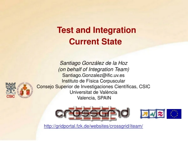
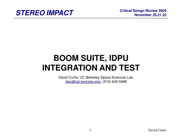
Integration, Test, and Calibration. Elliott Bloom Integration and Test and Calibration Manager elliott@slac.stanford.edu. I&T&C Organization Chart. I&T&C Manager Elliott Bloom WBS 4.1.9. I&T Engineer B. Grist WBS 4.1.9.1. Reliability & QA D. Marsh WBS 4.1.9.2. Instrument Operations

E N D
Integration, Test, and Calibration Elliott Bloom Integration and Test and Calibration Manager elliott@slac.stanford.edu
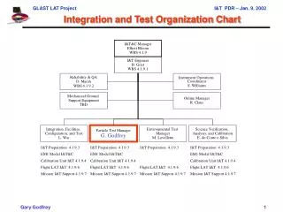
I&T&C Organization Chart I&T&C Manager Elliott Bloom WBS 4.1.9 I&T Engineer B. Grist WBS 4.1.9.1 Reliability & QA D. Marsh WBS 4.1.9.2 Instrument Operations Coordinator S. Williams Mechanical Ground Support Equipment TBD Online Manager R. Claus Integration, Facilities, Configuration, and Test O.Millican (Acting) Particle Test Manager G.Godfrey Environmental Test Manager M. Lovellette Science Verification, Analysis, and Calibration E. do Couto e Silva I&T Preparation 4.1.9.3 EM1 Model I&T&C Calibration Unit I&T 4.1.9.4 Flight LAT I&T 4.1.9.6 Mission I&T Support 4.1.9.7 I&T Preparation 4.1.9.3 EM1 Model I&T&C Calibration Unit I&T 4.1.9.4 Flight LAT I&T 4.1.9.6 Mission I&T Support 4.1.9.7 I&T Preparation 4.1.9.3 Flight LAT I&T 4.1.9.6 Mission I&T Support 4.1.9.7 I&T Preparation 4.1.9.3 EM1 Model I&T&C Calibration Unit I&T 4.1.9.4 Flight LAT I&T 4.1.9.6 Mission I&T Support 4.1.9.7
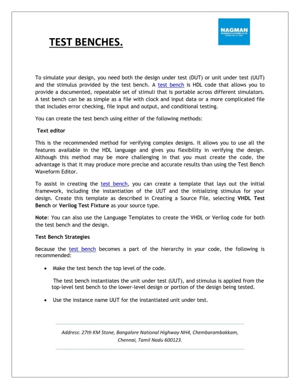
Integration and Test Subsystem Work Breakdown • 4.1.9.1 I & T Management • Coordinate I & T planning • Develop LAT I & T plan, to ensure flow of verification test activities • 4.1.9.2 Reliability and Quality Assurance • Collect subsystem verification test results • Manage LAT verification test assurance activities • 4.1.9.3 I & T Preparation - Integration, Facilities, Configuration, and Test, Particle Test, Environmental Test, Science Verification Analysis, & Calibration. • Prepare LAT I & T facilities • Develop calibration equipment • Develop Verification matrix and particle test plan • Develop environmental test plan • Develop Calibration plan
Integration and Test Subsystem Work Breakdown - 2 • EM1 Model I&T&C-Integration, Facilities, Configuration, and Test, Particle Test, Science Verification Analysis, & Calibration. (Currently no funding) • - Coordinate I&T&C tests with subsystem tests. • - Use subsystem calibration data to tune up I&T&C calibration program. • - Run cosmic rays on “assembled” EM1-EM2 unit at SLAC. • 4.1.9.4 Calibration Unit I & T -Integration, Facilities, Configuration, and Test, Particle Test, Science Verification Analysis, & Calibration. • Prepare for and integrate Calibration flight modules. • Prepare for and test QU with cosmic rays, positron, photon, and hadron beams. • Produce LAT calibration products for SAS from QU beam data. • 4.1.9.6 Flight LAT I&T- Integration, Facilities, Configuration, and Test, Particle Test, Environmental Test, Science Verification Analysis, & Calibration. • Prepare for integration of flight LAT; fabricate and test all mechanical GSE • Mechanically integrate flight LAT • Plan for and execute environmental verification testing • Support planning and execution of Observatory I&T
Integration and Test Subsystem Work Breakdown - 3 • 4.1.9.7 Mission I&T Support- Integration, Facilities, Configuration, and Test, Particle Test, Environmental Test, Science Verification Analysis, & Calibration. Produce a Working Instrument!
Integration, Test, and Calibration Activities • I & T “subsystem” is focal point of LAT integration activities • I & T & C team plans and manages activities. • TKR, CAL, and ACD subsystem teams provide support for Integration & Calibration. • Total effort involves: • I & T & C Subsystem • LAT integration planning and management. • Mechanical integration and GSE and EGSE development. • Plan Environmental tests and Execute. • Calibration particle beam and test equipment development. • Ground Verification and Calibration of LAT. • Commissioning of LAT in orbit. • Deliver a Working Instrument to IOC. • Mechanical Systems • Environmental test support. • LAT qualification testing analysis. • Electronics and Data Acquisition • LAT electrical integration. • Performance test planning and execution. • Flight software verification testing. • IOC Electrical GSE development, including calibration DAQ system • LAT performance test planning. • EGSE, and GSE operations and support during LAT I & T & C. • Science Analysis Software • Calibration analysis software development.
Integration Planning Activities • LAT integration planning • Planning for subsystem integration has been included in development of interfaces and LAT design integration • Developing concepts for integration EGSE and GSE. • LAT integration facilities • New clean room facilities have been built at SLAC for GLAST • Facilities include I&T infrastructure • Clean room with high bay • Storage for flight hardware • Environmental Tests • LAT thermal tests at SLAC. • Full suite of environmental tests at NRL. • Observatory integration support • I&T&C team has been involvedwith mission in investigating options forobservatory integration. • LAT and observatory requirecombined EGSE, GSE and coordinated plans environmental test plans. Concept of LAT Integration Frame
TKR/CAL: F1,2 from QU Mech: Flt Grid from Mech Flight LAT - FU TKR: F3-16 from TKR fab I&T: LAT Environmental tests (NRL) Acc I&T: LAT Calibration Airplane test Cal I&T: LAT Assembly, Test Acc CAL: F3-16 from CAL fab ACD: ACD to LAT I&T Mech: Flt Rad’s from Mech Obs: Vibe/Ac Observatory Acc Obs: T-V Observatory Acc Obs: EMI Observatory Acc Elec: Flt SIU’s to LAT I&T&C Elec: Qual SIU for EGSE LAT I&T&C Verification and Calibration Flow TKR: QA-B from TKR fab Calibration Unit -QU Vibe Random vibrate/sine sweep Acc Acceptance test level Ac Acoustic PFQ Proto-flight qual test level T-C Thermal-cycle at 1 atmosphere Qual Prototype qual test level T-V Thermal-vacuum cycle test Proof. Load test at proof level EMI Electro-magnetic interference test EM Engineering Model Engineering model tests TM Thermal model Qualification unit tests MM Mass model Flight unit/spare tests GSE Ground support equip. TKR: F1-2 from TKR fab I&T: Beam test QU – 4 towers Calibration CAL: QA-B from CAL fab CAL: F1-2 from CAL fab Elec: EM2 TEM, DAC, SIU I & T Responsibility
EGSE Areas of Responsibility • GLAST Mission • Scott Lambros • LAT • Large Area Telescope • Peter Michelson • EGSE • Electronics Ground Support Equipment • Gunther Haller • I&T&C • Integration and Test and Calibration • Elliott Bloom • IOC • Instrument Operation Center • Scott Williams Mission LAT EGSE I&T&C IOC Online
Tests & EGSE Configurations EM1- I&T&C only use data EM2 non-flight hardware QU –Qualification unit QU DAC non-flight hardware QU SIS Spacecraft Interface Simulator IPS Instrument Power Supply
Science Verification High Level Calibration Low Level Calibration Science Verification, Analysis and Calibration (SVAC) System Science Requirement Document (GLAST-00010) LAT Performance Specifications (LAT-SP-00010-1) LAT Verification Plan Calibration Requirements SVAC Plan Calibration Products SAS
SVAC Data (being reviewed by subsystems) Science verification High Level Calibration Low Level Calibration Subset of baseline calibrations Subset of performance calibrations • ACD • Detection Efficiency (CT1) • High Threshold detection (CT2) • TKR • Single Tower Alignment (CT4) • Multiple Tower Alignment (CT5) • LAT & Observatory Alignment (CT6) • CAL • PIN Diodes Optical Gain (CT10) • Light Attenuation (CT11) • Light Asymmetry (CT12) • ACD • Pedestals (CT3) • TKR • Noisy Strips (CT7) • Dead Strips (CT8) • Time-Over-Threshold (CT9) • CAL • Pedestals (CT13) • Energy range: Electronic Gain (CT14) • Energy range: Electronic Gain Occupancy (CT15) • Energy range: Integral non linearity (CT16) • Energy range: Differential non linearity (CT17) Effective Area Energy Resolution Point Spread Function Field of View Time Accuracy Background Rejection Deadtime Source Location Point Source Sensitivity GRB,AGN location GRB,AGN notification time
Particle test Verification Matrix • Requirements flow down from • LAT Science Requirements Document – Level II Specification LAT-SS-00010-1 (found in LAT-SS-9.1) • Summarized by the Instrument Scientist (Steve Ritz)
Altitude [Ft] BFEM L1T [Hz] Notes 0 25 Ground 25,000 540 Same rate as in orbit 35,000 900 Airplane flight 50,000 1175 Pfotzer max 127,000 540 ~Orbital rate Cosmics in Airplane (Psuedo Balloon Flight for Complete Flight Instrument, but Even Better) • Full LAT in an airplane (during airplane ride to NRL thermal vac ?) • L1T trigger rate measured in single tower during Balloon Flight • At 25,000 feet verify the flight hardware at orbital L1T rates • ~25 (BFEM size towers) x 540 Hz = 13.5 kHz • DAQ doesn’t crash • Software filter handles the rate and produces the expected downlink rate • Livetime is accurately measured • At 35,000 feet test the flight hardware at > orbital L1T rates • ~22 kHz saturates the LAT trigger • DAQ should not crash
Environmental Test Matrix LAT Modal Survey Acc Acc Acc M Rev date: 1 Oct 01
NRL Environmental Test Facility • Spacecraft Acoustic Reverberation Chamber • Sound pressure level of 153 dB through a range of 32-10,000 Hz • 30,000-lb force electrodynamic vibration exciter • Thermal High-Vacuum Chamber Facility • 18 ft diameter x 32 ft in length • Pressures below 1x10⁻⁶ Torr
NRL Environmental Test Facility • Spacecraft Vibration Test Facility • Largest table: 35,000-lb Spacecraft Vibration Test Facility • Largest table: 35,000-lb continuous sine or rms random vibration output and 105,000-lb peak random vibration • Frequency range 5 to 2000 Hz • EMI Test Chamber
prePDR Schedule 9:30 - 9:55 AM Bloom Intro/Overview 9:55 - 10:10 AM Grist - Top Level Cost Estimate, Top Level Schedule 10:10 - 10:30 AM Marsh - QA/Reliability 10:30 - 10:50 AM Claus - Online 10:50 - 11:10 AM Williams - IOC Coordination 11:10 - 11:30 AM Millican - Integration, Facilities, Configuration, and Test 11:30 - 11:40 AM Break 11:40 - 12:00 PM Godfrey - Particle Test 12:00 - 12:20 PM Lovellette - Environmental Test 12:20 - 12:40 PM do Couto e Silva - Calibration, Analysis and Science Verification 12:40 - 12:50 PM Bloom - Summary/Open issues and concerns. 12:50 - 1:30 PM Discussion