Download
1 / 21
210 likes | 349 Views
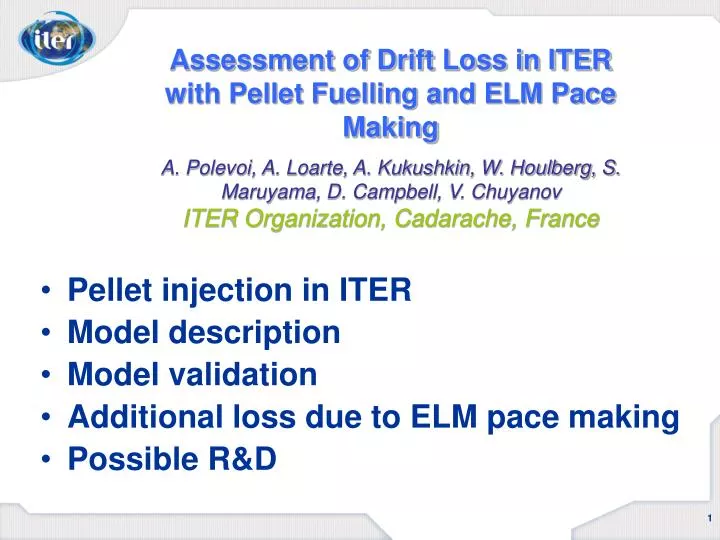
Assessment of Drift Loss in ITER with Pellet Fuelling and ELM Pace Making A. Polevoi, A. Loarte, A. Kukushkin, W. Houlberg, S. Maruyama, D. Campbell, V. Chuyanov ITER Organization, Cadarache, France. Pellet injection in ITER Model description Model validation

E N D
Assessment of Drift Loss in ITER with Pellet Fuelling and ELM Pace MakingA. Polevoi, A. Loarte, A. Kukushkin, W. Houlberg, S. Maruyama, D. Campbell, V. ChuyanovITER Organization, Cadarache, France • Pellet injection in ITER • Model description • Model validation • Additional loss due to ELM pace making • Possible R&D
Pellet fuelling is required in ITER fuelling from the edge saturates at low level ~ 16 Pa m3/s
ELM mitigation is required in ITER Predicted natural ELM energy loss in ITERDWELM~20 MJ (DWELM/Wped~ 20%) Permissible ELM energy loss DWELM= 1 MJ (DWELM/Wped~ 1% ) Background: - Erosion is negligible for: QELM < 0.5 MJ/m2 [Zhitlukhin et al, JNM 2007] - Strong in/out asymmetry:Pout/Pin = 1 : 2 [Eich et al, JNM 2007] - ELM affected area: Sin= 1.3 m2 DWELM= QELMx Sinx (1 + Pout/Pin) = = 0.5 MJ/m2 x 1.3 m2 x 1.5 1 MJ ELM losses DWELM = 1 MJ exist in JET experiments!!! Permissible ELM energy loss: DWELM= Maximal Load => x ELM affected surface x Peaking factor
ELM mitigation by pellet injection is possible Background • reduction of ELM loss DWELM for high ELM frequency fELM (JET, ASDEX-U): DWELM= (0.2—0.4) x Psep/ fELM => [Hermann , 2002; Urano et al, 2004] • full ELM control by pellet pace making with reduced DWELM is demonstrated (ASDEX-U) fELM= fpel= 20- 40 Hz => [Lang et al, 2005] =>fpel= fELM= 20- 40 Hz (ITER) R&D: - Confinement degradation with high-frequency pace making?
Independent HFS pellet fuelling and LFS ELM pace making in ITER is possible[Polevoi et al, 34th EPS, 2007 ] ITER HFS and LFS Injection Flight Tubes Layout
Requirements for ELM pace making pellets (l = Dped ?) Background • For ELM pace making pellet size, dpel and speed, vpel must provide penetrationto the top of pedestal l = Dped [ASDEX-U, Lang et al, 2005] • (for penetrationto the half of pedestal l = 0.5 Dped ) • [DIII-D, Baylor et al,35th EPS, 2008] • Ablation depth, l depends on the pellet size, dpel, speed vpel and plasma parameters, n, T along the path. It is higher for higher dpel, vpel and for lower n, T along the pellet paths. [ASDEX-U, Lang et al, 2005] R&D: Real requirements for pellet for ELM triggering?
Requirements for ELM pace making pellets (pedestal?) ITER pedestal • Reference ITER parameters n, T along the pellet paths.Top of pedestal is assumed to be located at 95% of poloidal magnetic flux NB:predicted pedestal parameters height (n,T) and width (Dped ) are rather uncertain. R&D: Pedestal parameters?
Requirements for pellets for ELM pace making: maximal speed • R&D: • Dependence of intact pellet speed on size of the bore of a guide tube; • Dependence of intact pellet speed on accumulation of residual gas in the tube for multiple frequent injection;
Requirements for pellets for ELM pace making: minimal size R&D: - Validation of ablation model for 2 – 4 mm pellets for vp,= 300-1000 m/s and n, T similar to ITER pedestal; - Accumulation of residual gas in the tube for multiple frequent injection (10% loss per pellet);
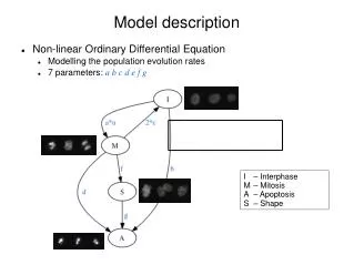
Pellet model description Simplified Mass Ablation and Relocation Treatment: [Polevoi, Shimada, PPCF, 43 (2001) p.15] - Ablation model by Kuteev: [Kuteev B, 1995, Nucl. Fusion 35 431] • Cloud size by Parks, et al [Parks P B, Sessions W D and Baylor L R 2000 Phys. Plasmas 7 1968] - Mass relocation by Strauss, Parks [Strauss H R and Park W, 1998, Phys. Plasmas 5 2676] R&D: Model validation for ablation, cloud size and relocation No time evolution: target state => final state
No time evolution: target state => final state Input/Output parameters: • Electron and electron temperatures, Te, Ti, keV • Ion species density, nH, (H pellet) nD, nT,(D,T,DT pellet) 1019 m-3 • Electron density, ne, 1019 m-3 Input – solid lines => Output – dashed lines HFS pellet injection in ITER-like plasma
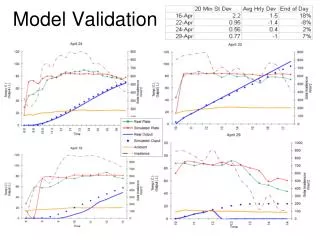
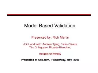
Model validation (examples) ASDEX-U HFS injection DIII- D LFS injection Satisfactory agreement
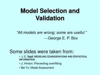
Model validation (examples) JT-60U HFS (Vert) injection DIII- D HFS injection [Takenaga et al, 2006, 33rd EPS] [Polevoi, Shimada, 2001] Satisfactory agreement
Additional loss due to ELM pace making(particle loss in ELM) R&D: Minimal pellet size for positive fuelling
Additional loss due to ELM pace making(energy loss due to drift of LFS pellet) Background: • Cooling starts before ELM triggering [ASDEX-U, G. Kocsis, 2008, 35th EPS] • Energy drop after pellet is higher for LHS than for HFS DWHFS/W = 1% => DWLFS/W = 8% [DIII-D, L. Baylor et al, 2000, PoP] R&D: Comparison of loss energy for HFS/LFS injection to extract drift loss Energy loss triggered by pellet [DIII-D, L. Baylor et al, 2000, PoP]
Additional loss due to ELM pace making(energy loss due to drift of LFS pellet) ITER: Assumption • LFS pellet is marginal for ELM triggering => ELM starts after ablation and cooling Calculation with SMART - Energy drop after pellet is higher for LHS than for HFS DWHFS/Wped= 1% (ELM) DWLFS/ Wped< 2.3% (ELM+drift) - Extra loss due to drift Pdrift = fLFSDWdrift R&D: Comparison of loss energy for HFS/LFS injection to extract drift loss Energy loss due to drift of LFS pellet
Possible R&D Injection system: • Dependence of intact pellet speed on size of the bore of a guide tube and on accumulation of residual gas in the tube for multiple frequent injection; • Accumulation of residual gas in the tube for multiple frequent injection (10% loss per pellet);
Possible R&D Plasma transport • Pedestal parameters prediction; • Confinement degradation with high-frequency pace making; • Real requirements for pellet for ELM triggering; • Influence of pellet induced modes; - Scaling DW = (0.2 -0.4??) P/f
Possible R&D Pellet physics • Validation of ablation, cloud size and relocation models for 2 – 5 mm pellets with vp, = 300 – 1000 m/s for n, T similar to ITER pedestal; • Minimal pellet size for positive fuelling; • Comparison of lost energy for HFS/LFS injection to extract drift loss
Summary • Pellet injection system is considered as the most prospective technique for fuelling and ELM mitigation in ITER • Present estimates of pellet injection for plasma fuelling and ELM pace making suggest that for safe operation without confinement degradation and negligible additional load on the divertor target the speed of LFS pellet have to be increased to 1000 m/s. • R&D is required to validate extrapolation of present day experiments assumed for the ITER pellet injection system design.