Download

1 / 18
180 likes | 318 Views
DATAFLOW ARHITEKTURE. Dataflow Processors - Motivation. In basic processor pipelining h azards limit performance Structural hazards Data hazards due to true dependences or name (false) dependences: anti and output dependences Control hazards Name dependences can be removed by:

E N D
Dataflow Processors- Motivation • In basic processor pipelining hazards limit performance • Structural hazards • Data hazards due to • true dependences or • name (false) dependences: anti and output dependences • Control hazards • Name dependences can be removed by: • compiler (register) renaming • renaming hardware advanced superscalars • single-assignment rule dataflow computers • Data hazards due to true dependences and control hazards can be avoided if succeeding instructions in the pipeline stem from different contexts dataflow computers, multithreaded processors
Dataflow vs. Control-Flow • von Neumann or control flow computing model: • a program is a series of addressable instructions, each of which either • specifies an operation along with memory locations of the operands or • it specifies (un)conditional transfer of control to some other instruction. • Essentially: the next instruction to be executed depends on what happened during the execution of the current instruction. • The next instruction to be executed is pointed to and triggered by the PC. • The instruction is executed even if some of its operands are not available yet (e.g. uninitialized). • Dataflow model: the execution is driven only by the availability of operand! • no PC and global updateable store • the two features of von Neumann model that become bottlenecks in exploiting parallelism are missing
Dataflow model of computation • Enabling rule: • An instruction is enabled (i.e. executable) if all operands are available. • Notice, that in von Neumann model, an instruction is enabled if it is pointed to by PC. • The computational rule or firing rule, specifies when an enabled instruction is actually executed. • Basic instruction firing rule: • An instruction is fired (i.e. executed) when it becomes enabled. • The effect of firing an instruction is the consumption of its input data (operands) and generation of output data (results). • Where are the structural hazards? Answer: ignored!!
Dataflow languages • Main characteristic: The single-assignment rule • A variable may appear on the left side of an assignment only once within the area of the program in which it is active. • Examples: VAL, Id, LUCID • A dataflow program is compiled into a dataflow graph which is a directed graph consisting of named nodes, which represent instructions, and arcs, which represent data dependences among instructions. • The dataflow graph is similar to a dependence graph used in intermediate representations of compilers. • During the execution of the program, data propagate along the arcs in data packets, called tokens. • This flow of tokens enables some of the nodes (instructions) and fires them.
x y z + 2 2 2 + 3 + 3 ¸ + ¸ Mean 2 - sqrt StDev Example in VAL • function Stats: computes the mean and standard deviation of three input values. function Stats(x,y,z: real returns real,real); let Mean := (x + y + z)/3; StDev := SQRT((x**2 + y**2 + z**2)/3 - Mean**2); in Mean, StDev endlet endfun
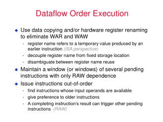
Instruction Processing Steps • DISPATCH: • Read operands from Register File (RF) and/or Rename Buffers (RRB) • Rename destination register and allocate RRB entry • Allocate Reorder Buffer (ROB) entry • Advance instruction to appropriate Reservation Station (RS) • EXECUTE: • RS entry monitors bus for register Tag(s) to latch in pending operand(s) • When all operands ready, issue instruction into Functional Unit (FU) and deallocate RS entry (no further stalling in execution pipe) • When execution finishes, broadcast result to waiting RS entries, RRB entry, and ROB entry • COMPLETE: • Update architected register from RRB entry, deallocate RRB entry, and if it is a store instruction, advance it to Store Buffer • Deallocate ROB entry and instruction is considered architecturally completed
Reservation Station Implementation • Reservation Stations: distributed vs. centralized • Wakeup: benefit to partition across data types • Select: much easier with partitioned scheme • Select 1 of n/4 vs. 4 of n Reorder Buffer Reservation Stations or Issue Queue Out of Order Out of Order In Order In Order
Reorder Buffer Implementation • Merge RS and ROB => Register Update Unit (RUU) • Inefficient, hard to scale Reorder Buffer Register Update Unit Out of Order Out of Order In Order In Order
Data Capture Reservation Station • Reservation Stations • Data capture vs. no data capture • Latter leads to “speculative scheduling”