Download
1 / 71
730 likes | 958 Views
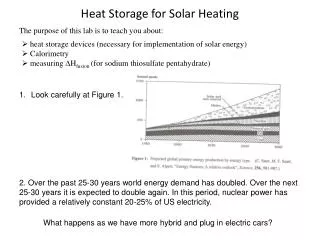
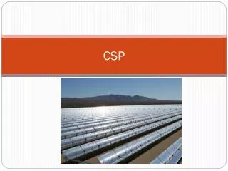
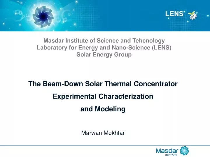
HEAT STORAGE FOR CSP. Masdar Institute of Science and Tehcnology Laboratory for Energy and Nano -Science (LENS) Solar Energy Group . The Beam-Down Solar Thermal Concentrator Experimental Characterization and Modeling Marwan Mokhtar. Concentrated Solar Power (CSP).

E N D
HEAT STORAGE FOR CSP Masdar Institute of Science and Tehcnology Laboratory for Energy and Nano-Science (LENS) Solar Energy Group The Beam-Down Solar Thermal ConcentratorExperimental Characterization and Modeling Marwan Mokhtar
Overview : Beam-Down Pilot Plant • Optical Design • Cavity Receiver • Ground Level Receiver • Segmented Secondary Reflector • Lower Wind Load • Lower Thermal Stress • Ganged-Type Heliostats • Three Banks of Mirrors • Lower Blocking and Shading Courtesy of TokyoTech
Overview : Beam-Down Pilot Plant • Optical Design • Cavity Receiver • Ground Level Receiver • Segmented Secondary Reflector • Lower Wind Load • Lower Thermal Stress • Ganged-Type Heliostats • Three Banks of Mirrors • Lower Blocking and Shading
Overview : Beam-Down Pilot Plant • Optical Design • Cavity Receiver • Ground Level Receiver • Segmented Secondary Reflector • Lower Wind Load • Lower Thermal Stress • Ganged-Type Heliostats • Three Banks of Mirrors • Lower Blocking and Shading Ganged-Type Heliostat Conventional Heliostat
Motivation Initial Project Objectives • Test design concepts • Simulation model verification • Feasibility of scaling up LENS Experimental Testing (March 2010) • Inadequacies in the measurement system • Heliostat concentration quality
Brief on the Measurement System Image of Flux Distribution on the Target Taken by the CCD Camera
Brief on the Measurement System Lambertian Target and Embedded Heat Flux Sensors
Heliostat Field Performance Test • Optical performance characterization of individual heliostats • Identify problems in the design or/and implementation • 6 days of testing • 33 heliostats • 5 data points per heliostat per day • 900 < flux maps to inspect
Selecting receiver aperture dimensions (r1,r2) Cumulative power intercepted by the receiver from the centroid until the radial distance (r), normalized by the total power.
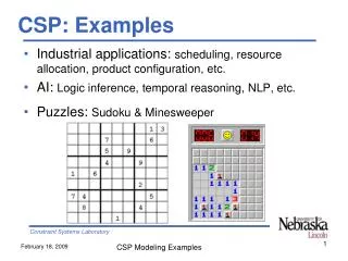
Main Observations 1) Inadequacies in the measurement system 2) Heliostat concentration quality
Concentrated Solar Flux Measurement System • Optical Method • Convenient • High Resolution 700x700 • Less Accurate • Requires a Uniform Lambertian Target • Measures Luminance (cd/m2)
Concentrated Solar Flux Measurement System • Heat Transfer Method • Flux Measured in (W/m2) • Accurate • Reliable • Low Resolution (Point Measurement) • Requires real-time corrections against ambient conditions
Concentrated Solar Flux Measurement System • The combination of the two system will give: • High resolution of optical method • Accuracy of the heat transfer method The final result is a heat “Flux Map” in (W/m2)
Problems in the Inherited System • Heat Transfer Method • ON/OFF Cooling system • Response to varying ambient conditions • Manufacturer calibration for different spectrum • Optical Method (Steve’s Thesis) • How Lambertian is the target ? • Degraded Quality of the target • CCD camera temperature response • and the correlation between the two systems (Steve’s Thesis)
Heat Flux Sensors (HFS) Courtesy of Kidd and Nelson 1995
Preliminary Testing of HFS RMSE= 115 W/m2
Heat Transfer Model of HFS G • We need measurement of • Reference Solar Radiation • Local Wind Speed • Ambient Temperature • Effective Sky Temperature • Cooling Water In/outlet Temperature
Results of Applying the Regression Model RMSE= 6.3 W/m2
Regression Model forced to be the same for all sensors
Results of Applying the Regression Model RMSE= 16.3 W/m2
Geometrical Optics Model • Very fast calculation compared to ray tracing • Allows the study of: • Optical aberrations • Optical errors and real sunshapes • Spillage, scattering, canting and other optical design parameters