Download
1 / 5
50 likes | 65 Views
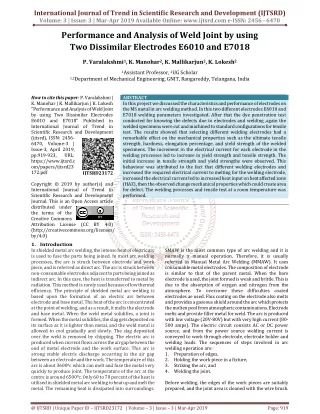
In this project we investigate the weld parameters of unbaked E7018 electrode low hydrogen covered electrode on MS weld metal. After welding the specimen, we conducted some prilimary tests on weld metal. This tests shows the weld metal characteristics and electrode performance. Also evaluate the effect of the current and voltage of the electrode on the weld metal. This electrode parameters shows effect of hardness and tensile strength of weld metal. Also we evaluate the effect of HAZ Heat Affected Zone on weld metal, there is a concern related to how the mechanical properties in the heat affected zone HAZ influence the behaviour of the joint. If electrode diameter and current increases the HAZ also increases. In this project for given dimensions 150 150 8 mm of weld metal we modify the current and size of the electrode and perform the welding operation on weld metal, and bring the results of weld joint in efficient manner. The welding and prilimary tests was performed at room temperature. Dr. B. Vijaya kumar | N. Yashwanth | P. Madhav | P. Srinath | N. Pradeep "Analysis and Investigation of Ms Weldment Using Unbaked E7018 Electrode " Published in International Journal of Trend in Scientific Research and Development (ijtsrd), ISSN: 2456-6470, Volume-3 | Issue-3 , April 2019, URL: https://www.ijtsrd.com/papers/ijtsrd23307.pdf Paper URL: https://www.ijtsrd.com/engineering/manufacturing-engineering/23307/analysis-and-investigation-of-ms-weldment--using-unbaked-e7018-electrode-/dr-b-vijaya-kumar<br>

E N D
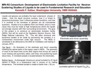
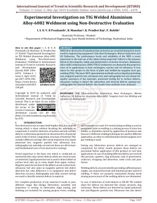
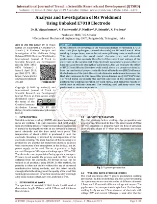
International Journal of Trend in Scientific Research and Development (IJTSRD) Volume: 3 | Issue: 3 | Mar-Apr 2019 Available Online: www.ijtsrd.com e-ISSN: 2456 - 6470 Analysis and Investigation of Ms Weldment Using Unbaked E7018 Electrode Dr. B. Vijaya kumar1, N. Yashwanth2, P. Madhav2, P. Srinath2, N. Pradeep2 1Professor, HOD, 2UG Scholar 1,2Department Mechanical Engineering, GNIT, Rangareddy, Telangana, India How to cite this paper:Dr. B. Vijaya kumar | N. Yashwanth | P. Madhav | P. Srinath | N. Pradeep "Analysis and Investigation of Ms Weldment Using Unbaked E7018 Electrode " Published in International Journal of Trend in Scientific Research and Development (ijtsrd), ISSN: 2456- 6470, Volume-3 | Issue-3, April 2019, pp.1168-1172, URL: https://www.ijtsrd.c om/papers/ijtsrd23 307.pdf Copyright © 2019 by author(s) and International Journal of Trend in Scientific Research and Development Journal. This is an Open Access article distributed under the terms of the Creative Commons Attribution License (CC BY 4.0) (http://creativecommons.org/licenses/ by/4.0) 1.INTRODUCTION Shielded metal arc welding (SMAW), also known as manual metal arc welding. It is least expensive, and most widely used arc welding process. This process produces coalescence of metals by heating them with an arc between a covered metal electrode and the base metal work piece. The temperature of about 40000c is produced to melt the electrode. Shielding is provided by decomposition of the electrode covering. The main function of the shielding is to protect the arc and the hot metal from chemical reaction with constituents of the atmosphere. In this both AC and DC power supply can be used. The arc is produced at high current 80amps to 300amps and voltage upto 20V to 70V. The electrode covering contains fluxing agents, scavengers. Pressure is not used in the process, and the filler metal is obtained from the electrode. All ferrous metals can be welded in all positions using SMAW. In this method, the porosity is often not visible without the use of advanced nondestructive testing methods, and this defect usually strongly affects the strength and the quality of the weld. This welding process is used for carbon steel, low alloy steel, high alloy steel, stainless steel, cast iron, and ductile iron. 2.EXPERIMENTAL WORK The specimen of material IS 2062 Grade B mild steel of dimensions length 150mm, width 150mm and thickness 8mm is taken. ABSTRACT In this project we investigate the weld parameters of unbaked E7018 electrode (low hydrogen covered electrode) on MS weld metal. After welding the specimen, we conducted some prilimary tests on weld metal. This tests shows the weld metal characteristics and electrode performance. Also evaluate the effect of the current and voltage of the electrode on the weld metal. This electrode parameters shows effect of hardness and tensile strength of weld metal. Also we evaluate the effect of HAZ (Heat Affected Zone) on weld metal, there is a concern related to how the mechanical properties in the heat-affected zone (HAZ) influence the behaviour of the joint. If electrode diameter and current increases the HAZ also increases. In this project for given dimensions ( 150*150*8 mm ) of weld metal we modify the current and size of the electrode and perform the welding operation on weld metal, and bring the results of weld joint in efficient manner. The welding and prilimary tests was performed at room temperature. IJTSRD23307 2.1 The test specimen before welding, edge preparation and groove preparation must be done. The groove angle of 30deg for two specimens is prepared with the help of grinding. Then we get a shape of ‘V’ when two specimens are joined together. GROOVE PREPARATION Fig 1: V groove preparation WELDING WITH E7018 ELECTRODE The weld specimens after V groove preparation welding process will be done on both face and root layer. For welding the specimens we use two electrodes of different diameter 2.5mm and 3.15mm with different voltage and current. The gap between the two specimen is upto 2mm. For face layer welding firstly we use 2.5mm diameter of electrode with voltage 20V and current 100amps is used after that for 2.2 @ IJTSRD | Unique Paper ID – IJTSRD23307 | Volume – 3 | Issue – 3 | Mar-Apr 2019 Page: 1168
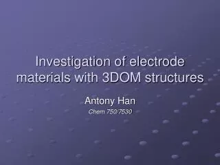
International Journal of Trend in Scientific Research and Development (IJTSRD) @ www.ijtsrd.com eISSN: 2456-6470 second layer we use 3.15mm diameter of electrode with voltage 25V and current 120amps is used. Next the root layer is welded with 2.5mm diameter of electrode with voltage 20V and current 100amps is used. After welding with help of spatter slag should be removed and with the wire brush the weld joint is cleaned. A.Pre-cleaning In this step the weldbead is cleaned to remove all traces of foreign material, grease, dirt etc. To get better results in inspection. Fig 4: Pre-cleaning the weld specimen B.Application of penetrate After pre-cleaning the weldbead, we apply penetrate on the surface of the weldbead. This penetrate is red in colour so it is helps us to detect defects easily. Fig 2: Welding the specimen with E7018 2.3 LEEB HARDNESS TEST Hardness testers using Leeb's method operate in a slightly different manner as compared to standard testing methods like Vickers, Rockwell or Brinell. The hardness is indirectly measured via the loss of energy of a so-called impact body. A mass is accelerated to the surface of the test object and impinges on it at a defined speed, i.e. kinetic energy. The impact creates a plastic deformation of the surface, i.e. an indentation, due to which the impact body loses part of its original speed - or energy. It will lose more speed by creating a bigger indentation and, thus, at softer material. Fig 5: Application of penetrate C.Dwell time The penetrate which we apply on weldbead to detect defects requires time to settle because of capillary action it may take 10 to 60 minutes to settle. So that we can get exact defects. D.Excess removal of penetrate After applying the penetrate on the weld surface the excess penetrate is removed so that we can get exact defects or else the penetrate applied on the weld surface will make the defects covered so that we can’t see defects. Fig 3: Leeb harness tester 2.4 DYE PENETRATE TEST Dye penetration test is also called as liquid penetrant testing. It is one of the earliest methods used for non-destructive inspection and has been a mainstay of practical ndt for many years. it is the most common ndt method (apart from visual inspection) used for the detection of surface breaking cracks in metal components. It is used on both face and root layer. The steps are: 1.Pre-cleaning 2.Application of penetrate 3.Dwell time 4.Excess removal of penetrate 5.Application of developer 6.Inspection 7.Post cleaning Fig 6: Excess removal of penetrate @ IJTSRD | Unique Paper ID - IJTSRD23307 | Volume – 3 | Issue – 3 | Mar-Apr 2019 Page: 1169
International Journal of Trend in Scientific Research and Development (IJTSRD) @ www.ijtsrd.com eISSN: 2456-6470 1.Pre-cleaning 2.Magnetization in longitudinal direction 3.Inspection 4.Demagnetization A.Pre-cleaning In this step the weldbead is cleaned to remove all traces of foreign material, grease, dirt etc. To get better results in inspection. E.Application of developer A thin layer of developer is then applied to the sample to draw penetrate trapped in flaws back to the surface where it is visible. Developers come in variety of forms that may be applied by dusting, dipping and spraying. Fig 7: Applying developer Fig 10: Pre-cleaning F.Inspection In this step we clearly see the defects which occur on weld bead after application of developer. B.Magnetization in longitudinal direction In this step first we need to spray contrast spray on the weld joint then the weld joint is placed in between the legs of magnetic yoke which has two legs with spacing of 8 inch and width minimum 3 inch. After the yoke switched on the magnetic lines travelles perpendicular to direction of current. Then the magnetic powder is sprinked on the weld joint in between yoke legs. So that we can see the defect of surface or sub surface. This process is done upto the weld joint length. ?Voltage: 220V ?Current: 2.2Amps ?Frequency: 50Hz Fig 8: Defects on face layer Fig 11: Applied contrast paint Fig 9: Defects on root layer 2.5 MAGNETIC PARTICLE TEST Magnetic particle testing (MPT) is one of the most widely used non-destructive testing. This method uses magnetic fields and small magnetic particles to detect flaws in specimen to be tested. The only requirement is that the component being inspected must be made of a ferromagnetic material. The magnetic penetration test can be done in following sequential manner Fig 11: Spraying magnetic powder @ IJTSRD | Unique Paper ID - IJTSRD23307 | Volume – 3 | Issue – 3 | Mar-Apr 2019 Page: 1170
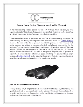
International Journal of Trend in Scientific Research and Development (IJTSRD) @ www.ijtsrd.com eISSN: 2456-6470 C.Inspection After spraying the magnetic particles due to magnetic yoke the magnetic lines which pass between two legs of yoke. If the defect is present the lines break and we can see the particles gather at that point. D.Demagnetization After identified the defects, we must demagnetize the metal. The demagnetization can be done with changing the direction of magnetic yoke. If any magnetization is present on the weld metal, further operations the efficiency may be reduced. The magnetization up to +3mm to -3mm is negligible. 2.6 RADIOGRAPHY TEST NDT techniques have been employed to test a material for surface or internal flaws without interfering in any way with its suitability for service. Radiography (X-rays or sometimes gamma rays) seems to be the most effective method and the experts are able to identify most types of defects in the images produced by this method. The method is based on the fact that the defective areas absorb more energy and thus the defects appear darker in the image. A detector is lined up with the beam on the other side of the item. The detector records x-rays or gamma rays that pass through the material. The thicker the material, the fewer x-rays or gamma rays can pass through. Because the material is thinner where there is a crack or flaw, more rays pass through that area. The detector captures the rays that pass through, which form a picture of the crack or flaw[5]. 2.7 BENDING TEST Bend test is one of the most important and commonly used destructive tests to determine the ductility and soundness (for the presence porosity, inclusion, penetration and other internal weld discontinuities) of the weld joint produced using under one set of welding conditions. The test is conducted on both face and root layer. Fig 13: Tensile test 3.RESULTS AND DISCUSSIONS 3.1 HARDNESS TEST RESULTS ON E7018 WELD METAL We get the following hardness values, while measuring the E7018 weld plate Table 1: Leeb Hardness Test values on E7018 weld metal Bas e met al (B1) Top 437 369 Top Middle 387 350 Middle Botto m m 1.RESULTS OF DYE PENETRATION TEST (DPT) On E7018 weld metal we observe following defects on face layer we observe pin holes (PH), on root layer we observe root under cut (RUC). 2.RESULTS OF MAGNETIC PARICLE TEST(MPI) MPI test is used to determine the surface and sub-surface defects on weldment. We conducted the MPI test on weldment welded by unbaked E7018 electrode we got two defects one is blow hole(BH) and the other is under cut (UC). Bas e met al (B2) 344 360 HA Z (H1 ) Weld ed area (W1) HA Z (H2 ) Positi on Positi on 352 371 346 408 Botto 340 348 454 334 365 Fig 14: MPI test defects on weldment 3.RESULTS OF RADIOGRAPHY TEST Fig 12: Bending test 2.8 TENSILE TEST Tensile strength is the maximum stress that a material can sustain in tension. In other words we can say the amount of applied load per cross sectional area that a material can withstand before failure. Mathematically it is calculated as the ratio of maximum tensile load to the original cross section area.[4] Tensile properties of the weld joints can be obtained either in ambient condition or in special environment (low temperature, high temperature, corrosion etc.) depending upon the requirement of the application using tensile test which is usually conducted at constant strain rate. Fig 15: Radiography test 4. RESULTS OF TENSILE TEST Tensile strength results on E7018 weld metal Load (KN) Deflection (mm) 127 30 5.RESULTS OF BENDING TEST Bending test results for E7018 weld metal Position Load (KN) Deflection (mm) Face 150 Root 55 90 85 @ IJTSRD | Unique Paper ID - IJTSRD23307 | Volume – 3 | Issue – 3 | Mar-Apr 2019 Page: 1171
International Journal of Trend in Scientific Research and Development (IJTSRD) @ www.ijtsrd.com eISSN: 2456-6470 6.CONCLUSION ?Recently developed low hydrogen basic coated electrodes deposit weld metal having improved toughness properties and low level hydrogen. These electrodes almost eliminate risk of cold cracking. ?Hydrogen control assumes hardenability increases. ?Hydrogen is an elusive element affecting cold cracking susceptibility in ferritic welds. ?To have longer shelf life and cut down cost of welding, fabricators prefer vacuum packed basic coated low hydrogen electrodes.[3] ?When low hydrogen (E7018) electrode is used, the weld is smooth as compared to the other electrode with less slag[1]. REFERENCES [1]Impermeable Low Hydrogen Covered Electrodes: Weld Metal, Slag, and Fumes Evaluation Cláudio TuraniVaz, Alexandre QueirozBracarense, Ezequiel CairesPereira Pessoa in Material science and Technology (volume 1) September 2012. IvanilzaFelizardo, criticality as the [2]Improvement of impact toughness of AWS E7018 weld metal by adding TiO2 nanoparticles to the electrode coating in M. P. Dhanukanano technology and advanced materials July 2008. [3]Md. Anis Raza, Sudhir Kumar Kashyap, Rakesh The effect of welding on mechanical and microstructural properties of material 2016. [4]Christopher T. Mgonja F. Ansari, in Service Life Estimation and Extension of Civil EngineeringStructures, 2017. @ IJTSRD | Unique Paper ID - IJTSRD23307 | Volume – 3 | Issue – 3 | Mar-Apr 2019 Page: 1172