Download
1 / 13
130 likes | 202 Views
Learn how to calculate heat transfer rates and fluid enthalpy balances, analyze temperature profiles, and design concentric pipe heat exchangers. Understand temperature driving forces, fluid characteristics, film coefficients, and tubing dimensions.

E N D
Concentric Pipe Heat Exchange Goals: By the end of today’s lecture, you should be able to: • Write the heat transfer rate equation and the fluid enthalpy balances for concentric pipe heat exchangers. • Describe the temperature profiles and calculate the true mean ∆T for parallel and countercurrent flow exchangers. • Use the heat transfer rate equation and the fluid enthalpy balances to make design calculations for concentric pipe heat exchangers.
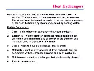
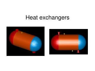
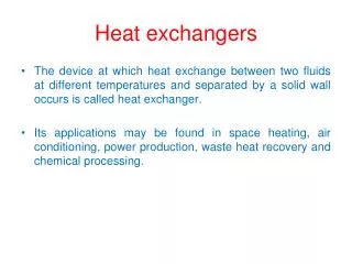
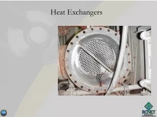
Concentric pipe (double pipe) heat exchangers Heat exchangers are used to transfer heat from a hot fluid to a cold fluid. Concentric pipe heat exchangers are the simplest and most easily analyzed configuration.
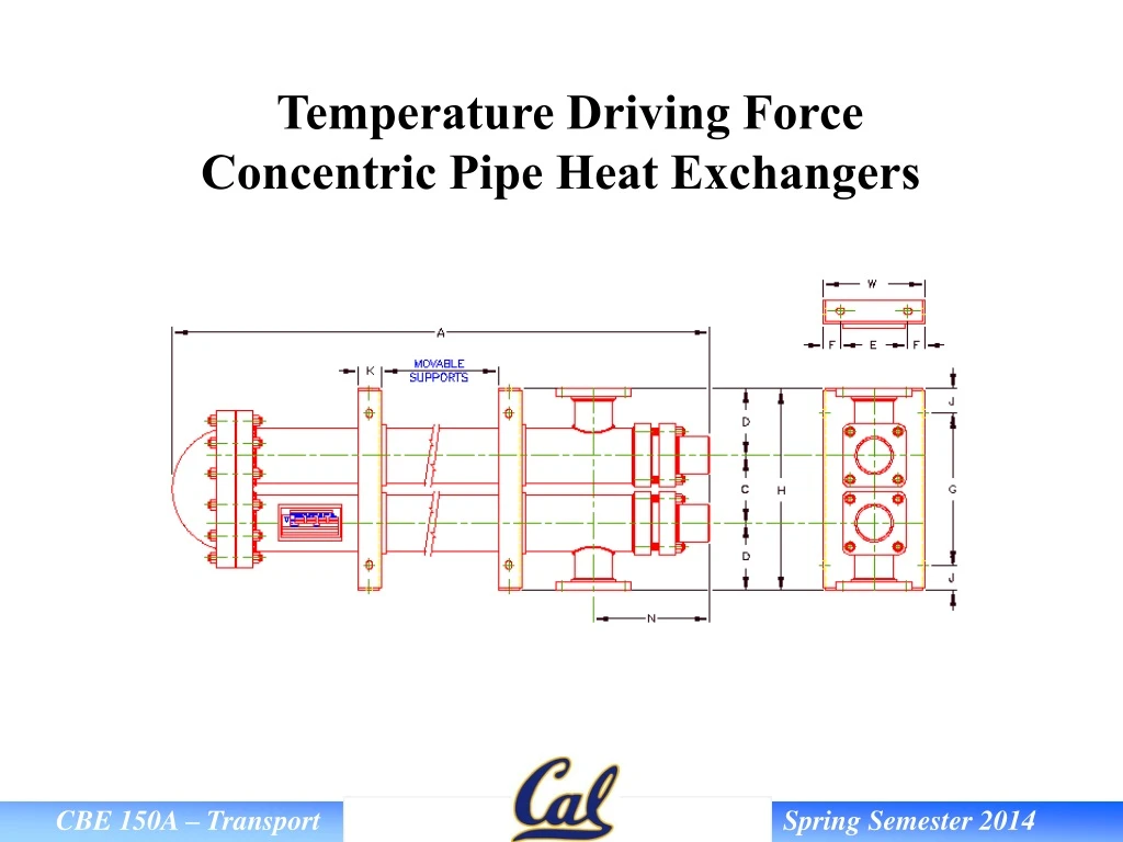
Consider a typical concentric pipe heat exchanger: Temperature Driving Force - DTlm Q = UA DTlm T = hot side fluid t = cold side fluid t1 T2 T1 t2
Temperature driving force derivation Assumptions: (1) Ui is constant (2) (Cp)hot and (Cp)cold are constant (3) heat loss to the surroundings is negligible (4) flow is steady state and parallel The overall heat transfer coefficient (U) does change with temperature, but the change is gradual. Thus, this assumption will hold for moderate temperature ranges.
Differential form of the steady-state heat balance: 1 2 3 4 5
Using Eqns 1 and 3 and substituting Eqn 5 for T: 6 7 8 Using solution for general form of integral and integrating between 0 and L and t1 and t2 yields:
Expand and simplify: 9 10 11 12 Substitute for (mCp) terms using Eqn 4:
Also, regardless of the exchanger design, if a phase change occurs, such as condensation or boiling (and the liquid is not subcooled or superheated), then: (Th)in = (Th)out or (Tc)in = (Tc)out and DTTM = DTLM Therefore, for concentric pipe heat exchangers and pure fluid condensers or evaporators, DTTM = DTLM. As we will find out later, this is NOT the case for shell-and-tube heat exchangers.
Example Problem Benzene is cooled from 141 F to 79 F in the inner pipe of a double-pipe exchanger. Cooling water flows counter-currently to the benzene, entering the jacket at 65 F and leaving at 75 F. The exchanger consists of an inner pipe of 7/8 inch BWG 16 copper tubing jacketed with a 1.5 inch Schedule 40 steel pipe. The linear velocity of the benzene is 5 ft/sec. Neglect the resistance of the wall and any scale on the pipe surfaces. Assume the L/D of both pipes is > 150. Compute: • Both the inside and outside film coefficients. • The overall coefficient based on the outside area of the inner pipe. • The LMTD