Download
1 / 47
510 likes | 734 Views
TEC 4000 X-Ray Diffraction System. (Use space bar to step through presentation). Introduction to the TEC 4000 X-ray Diffraction System. WHAT IS THE TEC MODEL 4000 X-RAY DIFFRACTION SYSTEM?. A complete system for measuring Residual Stress and Retained Austenite. The System consists of :

E N D
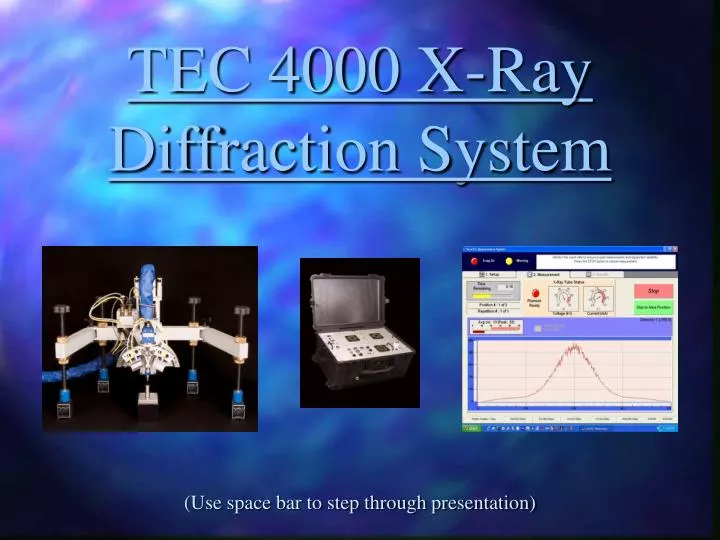
TEC 4000 X-Ray Diffraction System (Use space bar to step through presentation)
WHAT IS THE TEC MODEL 4000 X-RAY DIFFRACTION SYSTEM? • A complete system for measuring Residual Stress and Retained Austenite. • The System consists of : • Host Computer and peripherals. • TEC’s User Friendly SaraTEC Operating Software. • Model 4000 Workstation. • Model 4000 Diffractometer. • Customer Selected Options.
TEC 4000 Host Computer • The system is controlled by a Desktop or Notebook computer through Universal Serial Bus (USB) interface. • Lifetime SaraTEC software upgrades included.
TEC 4000 Workstation • Features of the TEC 4000 Workstation: • Operates on 110-220 Volts 50-60Hz. • System is designed for Laboratory and Field work • It has a self-contained, recirculating cooling system for X-ray tube cooling
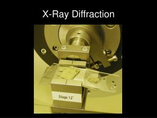
TEC 4000 Diffractometer • Features of the TEC 4000 Diffractometer: • Capable of -45° to 60° Ψ Rotation • Ω and Ψ Detector Orientations for Data Acquisition • An automated touch feature for precise Z-height adjustments • Swivel legs to accommodate the size and geometry of larger parts
TEC 4000 Safety Features • Low power x-ray tubes. • Fail safe safety system which includes: • One optical beam curtain supplied with all systems. • Fail Safe circuitry for all cabinet and diffractometer safety lights. • Circuitry for optional second safety device. • Key locks for x-ray power and safety circuits. • Meets requirements of NBS 111 and ANSI N43.2 for open beam operation.
TEC 4000 System Options • Standard system includes one PSPC detector, Cr X-ray tube, 156° bracket, Calibration mask, Vanadium Kß filter, and 1-5mm round collimators. • Options are: - 2 Detector system - Rectangular Collimators (0.5, 1, 1.5, 2, 3mm x 5mm) - Variety of X-ray Tubes - Cr, Cu, Co, Mn, Ti, Fe and V - Additional Brackets - 128 °,135 °,142 °,149 °, 152.5°, 160 ° - Automated Φ rotation table (360° rotation). - Automated X and Y axis tables (Standard 4” travel).
Main Setup Screen • This is where the parameters for making a measurement are set. • Setup parameters are: -Material Selection -Collimator Selection -Bracket Selection -Type of Radiation -Time (per Angle) -Measurement Type -Measurement Description -Position Queue (Ψ Tilt angles to be measured)
Material Selection • All of the materials that TEC has information on are stored in a Materials Library file in the software. Materials can be added, edited, or deleted in this selection tab.
Material Selection - Add • Materials can be added in this selection if the parameters are known. • If needed, TEC can assist with this information.
Any information that needs to be changed for a material is entered here. Materials Selection - Edit
The collimator size is selected according to type of surface (flat or curved). - Flat surface generally uses a round collimator. - Curved surface generally uses a rectangular collimator. Collimator Selection
Collimator selection allows you to rename collimators or add different sizes of collimators. (Round sizes in 1,2,3,4, and 5mm.) (Rectangular sizes are .5, 1.0,1.5,2.0, and 3 X 5mm) Collimator Selection - Edit
The bracket that is recommended for the material being measured is automatically determined when the material is selected. It can be changed manually to accommodate other diffraction peaks. Bracket Selection
If a bracket needs to be added it can be done with the ADD option. Bracket Selection - Add
This option is to let the software know what orientation the detector is in. The two options are Ω and Ψ. Detector Orientation Option
The TEC 4000 is capable of Ψ and Ω Detector Orientations. The orientations are limited to size and geometry (shape) of the part to be measured. Almost every part can be measured using one of the detector orientations. Detector Orientation Ψ (PSI) Orientation Ω (Omega) Orientation
The detector parameters are entered during a detector calibration. Once set, they do not need to be adjusted until the detector or detector electronics is replaced. Detector Parameters
The type of radiation being used is displayed here along with the power settings. X-Ray Tube Status
Measurement Description • The Measurement Description box allows the user to identify the part, location, and directions in which the measurements were taken.
This is where the target radiation (Tube Selection) and operating parameters for the X-ray tube are set. Edit X-Ray Tubes lists all the X-Ray tubes available by TEC. X-Ray Tube Parameters
Edit X-Ray Tubes selection displays the type of radiation source, the abbreviation, and also the type of filter needed for Kb suppression. Edit X-Ray Tubes
The Modify Positions selection is where the angles for Ψ, Z-height, X-Y table, and Φ Rotation table parameters are set. Modify Positions Option
Ψ angles and oscillation parameters are set in this tab. Single angles and multiple angles are entered here in degrees. Modify Measurement Positioning
Modify Measurement Positioning • Z-height is automatically calculated and set during the calibration procedure.
Modify Measurement Positioning • The X tab is for X table parameters. • It allows for table movement from left to right.
Modify Measurement Positioning • The Y tab is for Y table parameters. • It allows for table movement from front to back.
Modify Measurement Positioning • The Φ tab is for the Φ rotation table parameters. • It allows for table movement in 360° rotations.
Manual Control • The manual control selection allows the user to manually move the motors for Ψ, Z, X, Y, and Φ motors
Manual Control - Options • The Ψ Motor can be moved manually in increments of 1°, 5°, and 10° steps. • The Z Motor can be moved vertically in increments of .05, .1, and .5 inch increments.
Motor Control Keypad • The Motor Control Keypad allows the user to make motor movements for setting up the sample to be measured.
Options Selection • The Options selection displays the General, System, and Measurement information.
The General tab lets the user select where to save the measurements and automatically increments the file numbers for each measurement. Options - General Tab
Options - System Info • The System Info tab gives information pertaining to detector calibration information, motor operating ranges, and firmware versions.
Options - Movement Tab • The movement tab sets the Controlling Ψ Angle, shows the Motor Home Offset, Count Time Adjustment, and default settings for ROI and Peak Bounding.
Diagnostics Selection • The Diagnostics selection displays log files for Exposure, Error, and Status. • It also monitors hardware and safety system components.
Diagnostics - Hardware Tab • The hardware tab shows the type of X-ray power supply, and state of the X-ray power supply key switch. • It monitors the cooling water flow and tube temp. to protect the tube from overheating.
Diagnostics - Status Log Tab • The status log is generated to let the user know what events have taken place while the software is active. • It can be used in troubleshooting the system for hardware faults.
Diagnostics - Exposure Log Tab • This log is generated to let the user know how long the X-rays where energized. • It logs the time that the x-rays were turned on and off while the system is being operated.
Diagnostics - Error Log Tab • This log is generated when the system detects an error that the system encounters.
Diagnostics - Safety System Tab • The Safety features of this system are monitored here. • If the system encounters a problem, it will be displayed here and the system will display a safety system error message and will not proceed with a measurement.
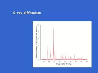
Display During Data Acquisition • A display of the spectra will be displayed during Data Acquisition in real time screen updates once the measurement has been started.
After Data Acquisition • After the data acquisition is finished, the corrected spectra is displayed and the launch analysis button will start the SaraTEC Analysis software and will display the results.
Benefits of using the TEC 4000 • Fast results allow production, statistical, and process control to improve quality and to reduce costs. • System can be easily and quickly reconfigured to analyze a wide variety of materials. • Nondestructive testing possible since parts often do not require sectioning. • Stress vs. Depth Profile is easily performed to evaluate peening intensity.
For further information regarding equipment and / or Lab services please contact: TEC Materials Testing Division 10737 Lexington Drive Knoxville, TN 37932 Phone: (865) 966-5856 or visit us on the web at:www.tecstress.com Email: info@tecstress.com